VEHICLE STABILITY CONTROL SYSTEM Slip Indicator Light does not Come ON
DESCRIPTION
Refer to Slip Indicator Light Remains ON Click here.
WIRING DIAGRAM
Refer to Slip Indicator Light Remains ON Click here.
INSPECTION PROCEDURE
PROCEDURE
-
CHECK IF SKID CONTROL ECU CONNECTOR IS SECURELY CONNECTED
-
Check if the skid control ECU connector is securely connected.
OK The connector is securely connected.
NG 
CONNECT CONNECTOR TO ECU CORRECTLY
OK 
-
-
CHECK BATTERY
-
Check the battery voltage.
Standard voltage 11 to 14 V
NG
CHECK OR REPLACE CHARGING SYSTEM OR BATTERY
OK
-
-
CHECK SLIP INDICATOR LIGHT
-
Turn the ignition switch to OFF and disconnect the skid control ECU connector.
-
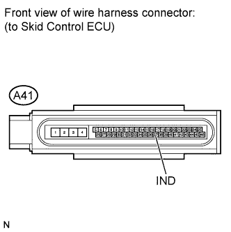
Ground terminal IND of the skid control ECU.
-
Turn the ignition switch to ON.
-
Check the SLIP Indicator light.
OK IND - GND Condition Illumination Condition Connecting ON Disconnecting OFF Tech Tips
-
When the VSC warning light comes on, ground failure or open circuits in the brake actuator should be considered.
-
When the VSC warning light does not come on, opens in the wire harness among the combination meters or abnormalities in the meter circuit should be considered.
-
NG 
CHECK HARNESS AND CONNECTOR (SKID CONTROL ECU - COMBINATION METER) Click here
OK
-
-
INSPECT SKID CONTROL ECU (IG1 TERMINAL)
-
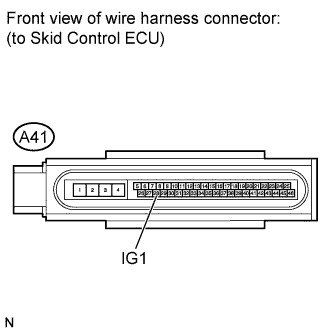
Disconnect the skid control ECU connector.
-
Turn the ignition switch to ON.
-
Measure the voltage according to the value(s) in the table below.
Standard voltage Tester Connection Switch Condition Specified Condition A41-28 (IG1) - Body ground Ignition switch ON 11 to 14 V
NG
REPAIR OR REPLACE HARNESS OR CONNECTOR (IG1 CIRCUIT)
OK
-
-
INSPECT SKID CONTROL ECU (GND TERMINAL)
-
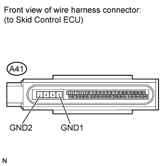
Turn the ignition switch to OFF.
-
Measure the resistance according to the value(s) in the table below.
Standard resistance Tester Connection Condition Specified Condition A41-4 (GND1) - Body ground Always Below 1 Ω A41-1 (GND2) - Body ground Always Below 1 Ω
NG
REPAIR OR REPLACE HARNESS OR CONNECTOR (GND CIRCUIT)
OK 
REPLACE BRAKE ACTUATOR ASSEMBLY Click here
-
-
CHECK HARNESS AND CONNECTOR (SKID CONTROL ECU - COMBINATION METER)
-
Turn the ignition switch to OFF.
-
Disconnect the skid control ECU connector and the combination meter connector.
-
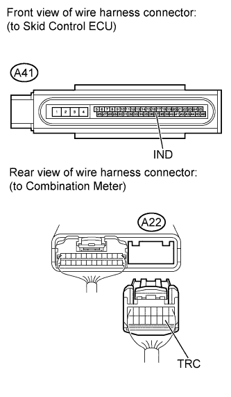
Measure the resistance according to the value(s) in the table below.
Standard resistance Tester Connection Condition Specified Condition A41-37 (IND) - A22-10 (TRC) Always Below 1 Ω A41-37 (IND) - Body ground Always 10 kΩ or higher
NG
REPAIR OR REPLACE HARNESS OR CONNECTOR
OK
-
-
INSPECT IG2 FUSE
-
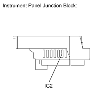
Remove the IG2 fuse from the instrument panel junction block.
-
Measure the resistance according to the value(s) in the table below.
Standard resistance Tester Connection Condition Specified Condition IG2 (15 A) fuse Always Below 1 Ω
NG
REPLACE IG2 FUSE
OK
-
-
CHECK HARNESS AND CONNECTOR (COMBINATION METER - BATTERY)
-
Disconnect the instrument panel junction block connector.
-
Turn the ignition switch to ON.
-
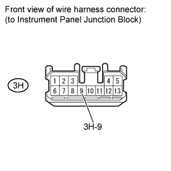
Measure the voltage according to the value(s) in the table below.
Standard voltage Tester Connection Switch Condition Specified Condition 3H-9 - Body ground Ignition switch ON 11 to 14 V
NG
REPAIR OR REPLACE HARNESS OR CONNECTOR
OK
REPLACE COMBINATION METER ASSEMBLY Click here
-