VEHICLE STABILITY CONTROL SYSTEM ABS Warning Light does not Come ON
DESCRIPTION
Refer to ABS Warning Light Remains ON Click here.
WIRING DIAGRAM
Refer to ABS Warning Light Remains ON Click here.
INSPECTION PROCEDURE
PROCEDURE
-
CHECK ABS WARNING LIGHT
-
Disconnect the skid control ECU connector.
-
Turn the ignition switch to ON.
-
Check that the ABS warning light comes on.
OK The ABS warning light comes on.
NG 
INSPECT IG2 FUSE Click here
OK 
REPLACE BRAKE ACTUATOR ASSEMBLY Click here
-
-
INSPECT IG2 FUSE
-
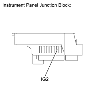
Remove the IG2 fuse from the instrument panel junction block.
-
Measure the resistance according to the value(s) in the table below.
Standard resistance Tester Connection Condition Specified Condition IG2 (15 A) fuse Always Below 1 Ω
NG 
REPLACE IG2 FUSE
OK 
-
-
CHECK HARNESS AND CONNECTOR (COMBINATION METER - BATTERY)
-
Disconnect the instrument panel junction block connector.
-
Turn the ignition switch to ON.
-
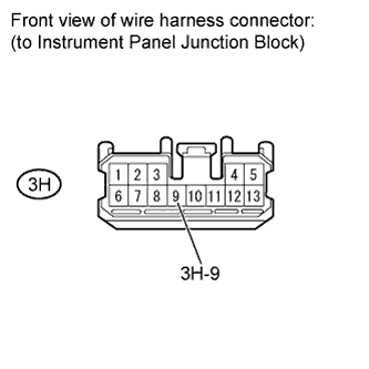
Measure the voltage according to the value(s) in the table below.
Standard voltage Tester Connection Switch Condition Specified Condition 3H-9 - Body ground Ignition switch ON 11 to 14 V
NG
REPAIR OR REPLACE HARNESS OR CONNECTOR
OK
-
-
CHECK HARNESS AND CONNECTOR (SKID CONTROL ECU - COMBINATION METER)
-
Disconnect the skid control ECU connector and the combination meter connector.
-
Inspect both the connector case and the terminal for deformation and corrosion.
OK No deformation or corrosion. -
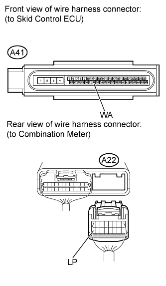
Measure the resistance according to the value(s) in the table below.
Standard resistance Tester Connection Condition Specified Condition A41-32 (WA) - A22-16 (LP) Always Below 1 Ω A41-32 (WA) - Body ground Always 10 kΩ or higher
NG
REPAIR OR REPLACE HARNESS OR CONNECTOR
OK
-
-
CHECK HARNESS AND CONNECTOR (COMBINATION METER - BODY GROUND)
-
Disconnect the instrument panel junction block connector.
-
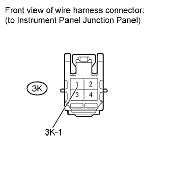
Measure the resistance according to the value(s) in the table below.
Standard resistance Tester Connection Condition Specified Condition 3K-1 - Body ground Always Below 1 Ω
NG
REPAIR OR REPLACE HARNESS OR CONNECTOR
OK
REPLACE COMBINATION METER ASSEMBLY Click here
-