VEHICLE STABILITY CONTROL SYSTEM ABS Warning Light Remains ON
DESCRIPTION
If any of the following is detected, the ABS warning light remains on:
-
The skid control ECU connectors are disconnected from the skid control ECU.
-
There is a malfunction in the skid control ECU internal circuit.
-
There is an open in the harness between the combination meter and the skid control ECU.
-
The ABS control system is defective.
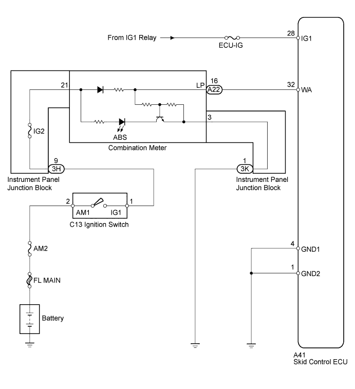
WIRING DIAGRAM
INSPECTION PROCEDURE
PROCEDURE
-
CHECK DTC
-
Turn the ignition switch to ON.
-
Check if the DTC is recorded Click here.
Result Result Proceed to DTC not output A DTC output B
B 
REPAIR CIRCUITS INDICATED BY OUTPUT DTCS Click here
A 
-
-
CHECK IF SKID CONTROL ECU CONNECTOR IS SECURELY CONNECTED
-
Check if the skid control ECU connector is securely connected.
OK The connector is securely connected.
NG
CONNECT CONNECTOR TO ECU CORRECTLY
OK
-
-
CHECK BATTERY
-
Check the battery voltage.
Standard voltage 11 to 14 V
NG
CHECK OR REPLACE CHARGING SYSTEM OR BATTERY
OK
-
-
CHECK ABS WARNING LIGHT
-
Turn the ignition switch to OFF and disconnect the skid control ECU connector.
-
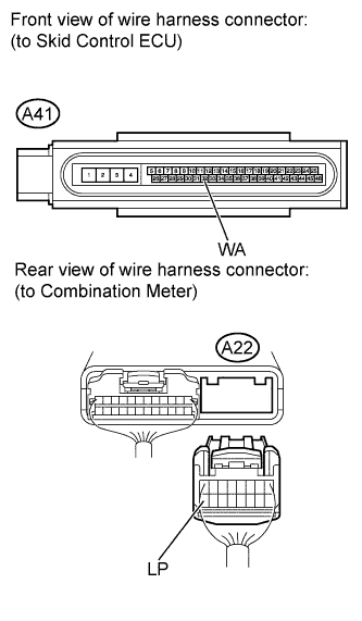
Ground terminal WA of the skid control ECU.
-
Turn the ignition switch to ON.
-
Check the ABS warning light.
OK WA- GND Condition Illumination Condition Connecting OFF Disconnecting ON Tech Tips
-
When the ABS warning light goes out, ground failure or open circuits in the brake actuator should be considered.
-
When the ABS warning light remains illuminated, opens in the wire harness among the combination meters or abnormalities in the meter circuit should be considered.
-
NG 
CHECK HARNESS AND CONNECTOR (SKID CONTROL ECU - COMBINATION METER) Click here
OK
-
-
INSPECT SKID CONTROL ECU (IG1 TERMINAL)
-
Disconnect the skid control ECU connector.
-
Turn the ignition switch to ON.
-
Measure the voltage according to the value(s) in the table below.
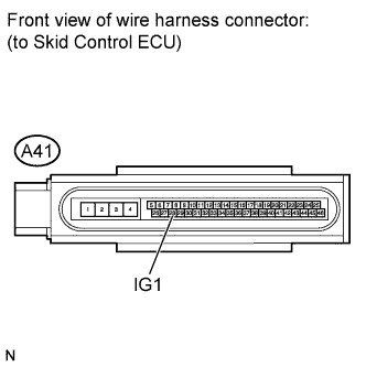
Standard voltage Tester Connection Switch Condition Specified Condition A41-28 (IG1) - Body ground Ignition switch ON 11 to 14 V
NG
REPAIR OR REPLACE HARNESS OR CONNECTOR (IG1 CIRCUIT)
OK
-
-
INSPECT SKID CONTROL ECU (GND TERMINAL)
-
Turn the ignition switch to OFF.
-
Measure the resistance according to the value(s) in the table below.
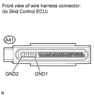
Standard resistance Tester Connection Condition Specified Condition A41-4 (GND1) - Body ground Always Below 1 Ω A41-1 (GND2) - Body ground Always Below 1 Ω
NG
REPAIR OR REPLACE HARNESS OR CONNECTOR (GND CIRCUIT)
OK 
REPLACE BRAKE ACTUATOR ASSEMBLY Click here
-
-
CHECK HARNESS AND CONNECTOR (SKID CONTROL ECU - COMBINATION METER)
-
Turn the ignition switch to OFF.
-
Disconnect the skid control ECU connector and the combination meter connector.
-
Measure the resistance according to the value(s) in the table below.
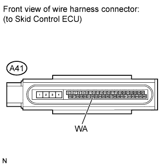
Standard resistance Tester Connection Condition Specified Condition A41-32 (WA) - A22-16 (LP) Always Below 1 Ω A41-32 (WA) - Body ground Always 10 kΩ or higher
NG
REPAIR OR REPLACE HARNESS OR CONNECTOR
OK
REPLACE COMBINATION METER ASSEMBLY Click here
-