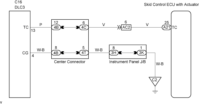
ANTI-LOCK BRAKE SYSTEM TC and CG Terminal Circuit
DESCRIPTION
Connecting terminals TC and CG of the DLC3 causes the skid control ECU to display 2-digit DTCs by flashing the ABS warning light.
WIRING DIAGRAM
INSPECTION PROCEDURE
PROCEDURE
-
CHECK DLC3 TERMINAL VOLTAGE (TC TERMINAL)
-
Turn the ignition switch to the ON position.
-
Measure the voltage.
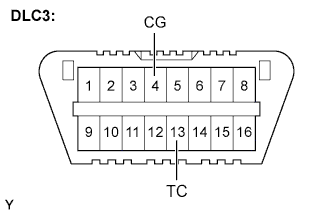
Standard Voltage Tester Connection Specified Condition C16-13 (TC) - C16-4 (CG) 10 to 14 V
NG 
CHECK HARNESS AND CONNECTOR (DLC3 - BODY GROUND) Click here
OK 
-
-
CHECK HARNESS AND CONNECTOR (SKID CONTROL ECU - DLC3)
-
Disconnect the skid control ECU connector.
-
Measure the resistance.
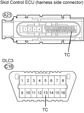
Standard Resistance Tester Connection Specified Condition A21-25 (TC) - C16-13 (TC) Below 1 Ω A21-25 (TC) - Body ground 10 kΩ or higher
NG 
REPAIR OR REPLACE HARNESS AND CONNECTOR
OK 
REPLACE BRAKE ACTUATOR
-
-
CHECK HARNESS AND CONNECTOR (DLC3 - BODY GROUND)
-
Measure the resistance.
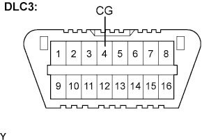
Standard Resistance Tester Connection Specified Condition C16-4 (CG) - Body ground Below 1 Ω
NG
REPAIR OR REPLACE HARNESS AND CONNECTOR
OK
-
-
CHECK HARNESS AND CONNECTOR (SKID CONTROL ECU - DLC3)
-
Disconnect the skid control ECU connector.
-
Measure the resistance.
Standard Resistance Tester Connection Specified Condition A21-25 (TC) - C16-13 (TC) Below 1 Ω A21-25 (TC) - Body ground 10 kΩ or higher
NG
REPAIR OR REPLACE HARNESS AND CONNECTOR
OK
REPLACE BRAKE ACTUATOR
-