ANTI-LOCK BRAKE SYSTEM Brake Warning Light Remains ON
DESCRIPTION
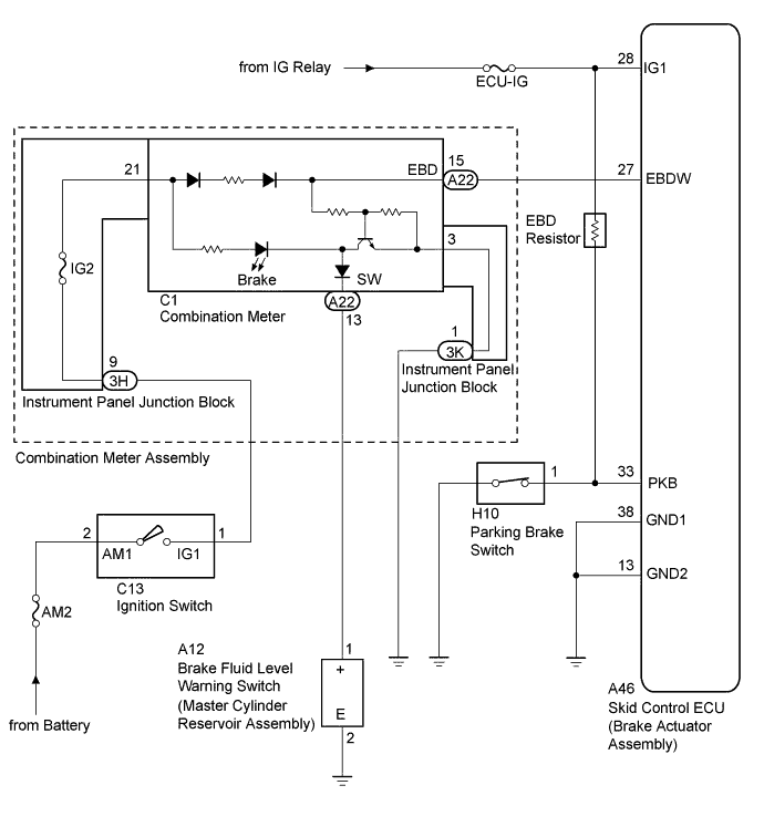
The Brake warning light lights up when there is insufficient brake fluid, the parking brake is applied or the EBD is defective.
WIRING DIAGRAM
INSPECTION PROCEDURE
Note
Inspect the fuses for circuits related to this system before performing the following inspection procedure.
Tech Tips
Before releasing the parking brake, set chocks to hold the vehicle for safety.
PROCEDURE
-
CHECK BRAKE FLUID LEVEL
-
Check the amount of brake fluid in the brake reservoir.
OK Brake fluid level is correct.
NG 
ADD BRAKE FLUID
OK 
-
-
CHECK FOR DTC
-
Check if any DTCs are output.
Result Result Proceed to DTC not output A DTC output B
B
REPAIR CIRCUIT INDICATED BY OUTPUT DTCS
A
-
-
CHECK IF SKID CONTROL ECU CONNECTOR IS SECURELY CONNECTED
-
Check if the skid control ECU (brake actuator assembly) connector is securely connected.
OK The connector is securely connected.
NG
CONNECT CONNECTOR TO ECU CORRECTLY
OK
-
-
CHECK BATTERY
-
Check the battery voltage.
Standard voltage 11 to 14 V
NG
CHECK OR REPLACE CHARGING SYSTEM OR BATTERY
OK
-
-
CHECK BRAKE WARNING LIGHT
-
Turn the ignition switch off.
-
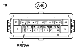
Text in Illustration *a Front view of wire harness connector
(to Skid Control ECU (Brake Actuator Assembly))
Disconnect the skid control ECU (brake actuator assembly) connector.
-
Ground terminal EBDW of the skid control ECU (brake actuator assembly).
-
Turn the ignition switch to ON.
-
Check the Brake warning light.
OK Condition Illumination Condition A46-27 (EBDW) - Body ground Connected OFF A46-27 (EBDW) - Body ground Disconnected ON Tech Tips
-
When the Brake warning light goes out, ground failure or open circuits in the brake actuator should be considered.
-
When the Brake warning light remains illuminated, opens in the wire harness among the combination meters or abnormalities in the meter circuit should be considered.
-
NG 
CHECK HARNESS AND CONNECTOR (SKID CONTROL ECU - COMBINATION METER ASSEMBLY) Click here
OK
-
-
CHECK HARNESS AND CONNECTOR (IG1 TERMINAL)
-
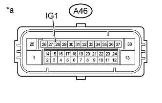
Text in Illustration *a Front view of wire harness connector
(to Skid Control ECU (Brake Actuator Assembly))
Measure the voltage according to the value(s) in the table below.
Standard Voltage Tester Connection Switch Condition Specified Condition A46-28 (IG1) - Body ground Ignition switch ON 11 to 14 V
NG
REPAIR OR REPLACE HARNESS OR CONNECTOR (IG1 CIRCUIT)
OK
-
-
CHECK HARNESS AND CONNECTOR (GND1, GND2 TERMINAL)
-
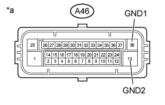
Text in Illustration *a Front view of wire harness connector
(to Skid Control ECU (Brake Actuator Assembly))
Measure the resistance according to the value(s) in the table below.
Standard Resistance Tester Connection Condition Specified Condition A46-38 (GND1) - Body ground Always Below 1 Ω A46-13 (GND2) - Body ground Always Below 1 Ω
NG
REPAIR OR REPLACE HARNESS OR CONNECTOR (GND1, GND2 CIRCUIT)
OK
-
-
INSPECT PARKING BRAKE SWITCH ASSEMBLY
-
Remove the parking brake switch assembly Click here.
-
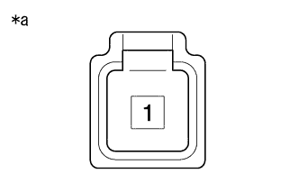
Text in Illustration *a Component without harness connected
(Parking Brake Switch Assembly)
Measure the resistance according to the value(s) in the table below.
Standard Resistance Tester Connection Switch Condition Specified Condition 1 - Body ground Parking brake switch assembly ON (Switch pin free) Below 1 Ω Parking brake switch assembly OFF (Switch pin pushed in) 10 kΩ or higher
NG
REPLACE PARKING BRAKE SWITCH ASSEMBLY
OK
-
-
CHECK HARNESS AND CONNECTOR (SKID CONTROL ECU - PARKING BRAKE SWITCH ASSEMBLY)
-
Disconnect the A46 skid control ECU (brake actuator assembly) connector.
-
Measure the resistance according to the value(s) in the table below.
Standard Resistance Tester Connection Condition Specified Condition A46-33 (PKB) - H10-1 Always Below 1 Ω A46-33 (PKB) - Body ground Always 10 kΩ or higher
NG
REPAIR OR REPLACE HARNESS OR CONNECTOR
OK 
REPLACE BRAKE ACTUATOR ASSEMBLY Click here
-
-
CHECK HARNESS AND CONNECTOR (SKID CONTROL ECU - COMBINATION METER ASSEMBLY)
-
Disconnect the A46 skid control ECU (brake actuator assembly) connector and the A22 combination meter assembly connector.
-
Measure the resistance according to the value(s) in the table below.
Standard Resistance Tester Connection Condition Specified Condition A46-27 (EBDW) - A22-15 (EBD) Always Below 1 Ω A46-27 (EBDW) - Body ground Always 10 kΩ or higher
NG
REPAIR OR REPLACE HARNESS OR CONNECTOR
OK
-
-
INSPECT BRAKE FLUID LEVEL WARNING SWITCH (BRAKE MASTER CYLINDER RESERVOIR ASSEMBLY)
-
Disconnect the brake fluid level warning switch (brake master cylinder reservoir assembly) connector.
-
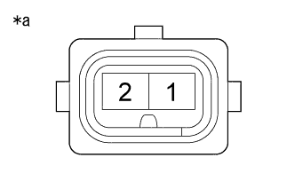
Text in Illustration *a Component without harness connected
(Brake Fluid Level Warning Switch (Brake Master Cylinder Reservoir Assembly))
Measure the resistance according to the value(s) in the table below.
Standard Resistance Tester Connection Switch Condition Specified Condition 1 (+) - 2 (E) Switch OFF (Float UP) 10 kΩ or higher Switch ON (Float DOWN) Below 1 Ω
NG
REPLACE BRAKE MASTER CYLINDER RESERVOIR SUB-ASSEMBLY
OK
-
-
CHECK HARNESS AND CONNECTOR (COMBINATION METER ASSEMBLY - BRAKE FLUID LEVEL WARNING SWITCH)
-
Disconnect the A22 combination meter assembly connector.
-
Measure the resistance according to the value(s) in the table below.
Standard Resistance Tester Connection Condition Specified Condition A22-13 (SW) - A12-1 (+) Always Below 1 Ω A22-13 (SW) - Body ground Always 10 kΩ or higher A12-2 (E) - Body ground Always 10 kΩ or higher
NG
REPAIR OR REPLACE HARNESS OR CONNECTOR
OK
REPLACE COMBINATION METER ASSEMBLY Click here
-