ANTI-LOCK BRAKE SYSTEM Brake Warning Light does not Come ON
DESCRIPTION
Refer to Brake Warning Light Remains ON Click here.
WIRING DIAGRAM
Refer to Brake Warning Light Remains ON Click here.
INSPECTION PROCEDURE
Note
Inspect the fuses for circuits related to this system before performing the following inspection procedure.
PROCEDURE
-
CHECK BRAKE WARNING LIGHT
-
Disconnect the skid control ECU connector.
-
Turn the ignition switch to ON.
-
Check that the Brake warning light comes on.
OK The Brake warning light comes on.
NG 
OK 
REPLACE BRAKE ACTUATOR ASSEMBLY Click here
-
-
CHECK HARNESS AND CONNECTOR (COMBINATION METER ASSEMBLY - BATTERY)
-
Disconnect the instrument panel Junction block assembly connector.
-
Measure the voltage according to the value(s) in the table below.
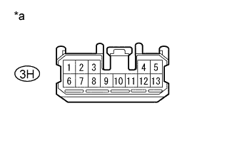
Standard Voltage Tester Connection Condition Specified Condition 3H-9 - Body ground Ignition switch ON 11 to 14 V Text in Illustration a* Front view of wire harness connector
(combination meter assembly.)
NG 
REPAIR OR REPLACE HARNESS OR CONNECTOR
OK 
-
-
CHECK HARNESS AND CONNECTOR (SKID CONTROL ECU - COMBINATION METER)
-
Disconnect the A46 skid control ECU (brake actuator assembly) connector and the A22 combination meter assembly connector.
-
Measure the resistance according to the value(s) in the table below.
Standard Resistance Tester Connection Condition Specified Condition A46-27 (EBDW) - A22-15 (EBD) Always Below 1 Ω A46-27 (EBDW) - Body ground Always 10 kΩ or higher
NG
REPAIR OR REPLACE HARNESS OR CONNECTOR
OK
-
-
CHECK HARNESS AND CONNECTOR (COMBINATION METER ASSEMBLY - BODY GROUND)
-
Disconnect the instrument panel junction block assembly connector.
-
Measure the resistance according to the value(s) in the table below.
Standard resistance Tester Connection Condition Specified Condition 3K-1 - Body ground Always Below 1 Ω
NG
REPAIR OR REPLACE HARNESS OR CONNECTOR
OK
REPLACE COMBINATION METER ASSEMBLY Click here
-