ANTI-LOCK BRAKE SYSTEM ABS Warning Light does not Come ON
WIRING DIAGRAM
INSPECTION PROCEDURE
PROCEDURE
-
CHECK ABS WARNING LIGHT
-
When using an intelligent tester:
-
Connect the intelligent tester.
-
Turn the ignition switch to the ON position.
-
Turn the tester ON.
-
Select the "ABS Warning Light " in the ACTIVE TEST and operate the ABS warning light by using the intelligent tester.
Select the following menu items: Chassis / ABS/VSC/TRC / Active Test.
Item Vehicle Condition / Test Details Diagnostic Note ABS Warning Light Turns ABS warning light ON / OFF Observe combination meter -
Check that "ON" and "OFF" of the ABS warning light can be shown on the combination meter by the intelligent tester.
OK The ABS warning light turns ON or OFF in accordance with the intelligent tester.
-
-
When not using an intelligent tester:
Tech Tips
By disconnecting the ECU connector, the ABS warning light comes on (as the ABS warning light circuit in the meter is an active circuit).
-
Turn the ignition switch to OFF.
-
Disconnect the skid control ECU connector.
-
Turn the ignition switch to the ON position.
-
Check that the ABS warning light comes on.
OK The ABS warning light comes on.
-
NG 
INSPECT FUSE (IG2) Click here
OK 
REPLACE BRAKE ACTUATOR
-
-
INSPECT FUSE (IG2)
-
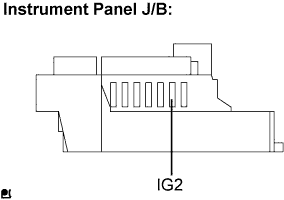
Remove the IG2 fuse from the instrument panel J/B.
-
Measure the resistance.
Standard Resistance Below 1 Ω
NG 
REPLACE FUSE
OK 
-
-
CHECK HARNESS AND CONNECTOR (SKID CONTROL ECU - COMBINATION METER)
-
Disconnect the skid control ECU connector and the combination meter connector.
-
Inspect both the connector case and the terminal for deformation and corrosion.
OK No deformation or corrosion. -
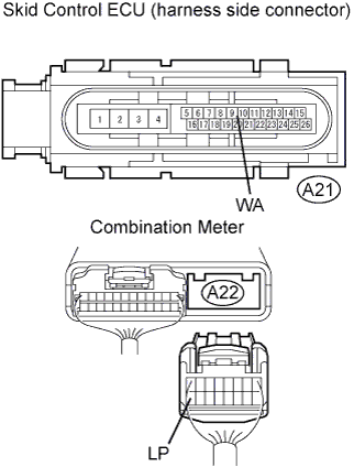
Measure the resistance.
Standard Resistance Tester Connection Specified Condition A21-22 (WA) - A22-16 (LP) Below 1 Ω A21-22 (WA) - Body ground 10 kΩ or higher
NG
REPAIR OR REPLACE HARNESS AND CONNECTOR
OK
-
-
CHECK HARNESS AND CONNECTOR (COMBINATION METER ASSEMBLY - BATTERY)
-
Disconnect the instrument panel J/B connector 3H.
-
Turn the ignition switch to the ON position.
-
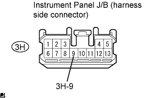
Measure the voltage.
Standard Voltage Tester Connection Specified Condition 3H-9 - Body ground 10 to 14 V
NG
REPAIR OR REPLACE HARNESS AND CONNECTOR
OK
REPLACE COMBINATION METER ASSEMBLY
-