ANTI-LOCK BRAKE SYSTEM, Diagnostic DTC:C1417

| DTC Code | DTC Name |
|---|---|
| C1417 | High Power Supply Voltage Malfunction |
DESCRIPTION
If a malfunction is detected in the power supply circuit, the skid control ECU (brake actuator assembly) stores this DTC and the fail-safe function prohibits ABS operation.
This DTC is stored when the +BS terminal voltage deviates from the DTC detection condition due to a malfunction in the power supply or charging circuit such as the battery or alternator circuit, etc.
| DTC No. | DTC Detection Condition | Trouble Area |
|---|---|---|
| C1417 | +BS terminal voltage is more than 16.5 V for 1 second or more. |
|
WIRING DIAGRAM
Refer to DTC C1241 Click here.
INSPECTION PROCEDURE
Note
Inspect the fuses for circuits related to this system before performing the following inspection procedure.
PROCEDURE
-
CHECK BATTERY
-
Check the battery voltage.
Standard Voltage 11 to 14 V
NG 
CHECK OR REPLACE CHARGING SYSTEM COMPONENT OR BATTERY Click here
OK 
-
-
CHECK HARNESS AND CONNECTOR (POWER SOURCE TERMINAL)
-
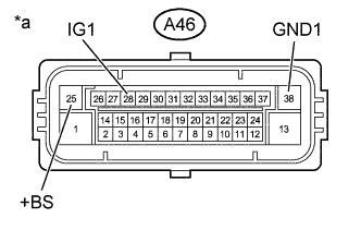
Text in Illustration *a Front view of wire harness connector
(to Skid Control ECU (Brake Actuator Assembly))
Disconnect the skid control ECU (brake actuator assembly) connector.
-
Measure the voltage according to the value(s) in the table below.
Standard Voltage Tester Connection Condition Specified Condition A46-25 (+BS) - Body ground Always 11 to 14 V A46-25 (+BS) - A46-38 (GND1) Always 11 to 14 V A46-28 (IG1) - Body ground Ignition switch ON 11 to 14 V A46-28 (IG1) - A46-38 (GND1) Ignition switch ON 11 to 14 V
NG
REPAIR OR REPLACE HARNESS OR CONNECTOR (POWER SOURCE CIRCUIT)
OK
-
-
RECONFIRM DTC
-
Reconnect the skid control ECU (brake actuator assembly) connector.
-
Clear the DTCs Click here.
-
Turn the ignition switch off.
-
Start the engine.
-
Perform a road test.
-
Check if the same DTC is output Click here.
Result Result Proceed to DTC C1417 is not output. A DTC C1417 is output. B Tech Tips
If troubleshooting has been carried out according to Problem Symptoms Table, refer back to the table and proceed to the next step before replacing parts Click here.
B
REPLACE BRAKE ACTUATOR ASSEMBLY Click here
A 
CHECK FOR INTERMITTENT PROBLEMS
-