ANTI-LOCK BRAKE SYSTEM, Diagnostic DTC:C1300/62

| DTC Code | DTC Name |
|---|---|
| C1300/62 | ABS ECU Malfunction |
DESCRIPTION
| DTC No. | DTC Detecting Condition | Trouble Area |
|---|---|---|
| C1300/62 | Internal failure of skid control ECU control unit. | Skid control ECU |
INSPECTION PROCEDURE
PROCEDURE
-
RECONFIRM DTC
-
Clear the DTCs Click here.
-
Turn the ignition switch to the ON position.
-
Check if the same DTC is recorded.
Result DTC C1300/62 output A DTC other than C1300/62 output B
B 
REPAIR CIRCUIT INDICATED BY OUTPUT DTC
A 
-
-
CHECK SKID CONTROL ECU TERMINAL VOLTAGE
-
When using an intelligent tester:
-
Connect the intelligent tester to the DLC3.
-
Turn the tester ON.
-
Read the value using the intelligent tester.
Select the following menu items: Chassis / ABS/VSC/TRC / Data List.
Item Measurement Item : Range (Display) Normal Condition ECU IG Power Voltage ECU power supply voltage : TOO LOW / NORMAL / TOO HIGH TOO HIGH: 14.0 V or more
NORMAL: 9.5 to 14.0 V
TOO LOW: Below 9.5 V
-
Read the voltage condition output from the ECU displayed on the intelligent tester.
OK "Normal" is displayed.
-
-
When not using an intelligent tester:
-
Disconnect the skid control ECU connector.
-
Turn the ignition switch to the ON position.
-
Measure the voltage.
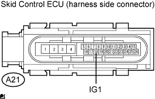
Standard Voltage Tester Connection Condition Specified Condition A21-18 - (IG1) - Body ground Ignition switch ON (IG) 10 to 14 V
-
NG
REPAIR OR REPLACE HARNESS AND CONNECTOR
OK
-
-
CHECK HARNESS AND CONNECTOR (SKID CONTROL ECU - BODY GROUND)
-
Inspect the skid control ECU connector fitting for any defects.
-
Disconnect the skid control ECU connector.
-
Inspect both the connector case and the terminal for deformation and corrosion.
OK No deformation or corrosion. -
Measure the resistance.
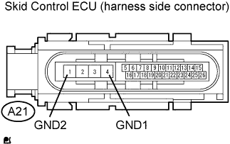
Standard Resistance Tester Connection Specified Condition A21-4 (GND1) - Body ground Below 1 Ω A21-1 (GND2) - Body ground Below 1 Ω
NG
REPAIR OR REPLACE HARNESS AND CONNECTOR
OK 
REPLACE BRAKE ACTUATOR
-