ANTI-LOCK BRAKE SYSTEM, Diagnostic DTC:C1249/58

| DTC Code | DTC Name |
|---|---|
| C1249/58 | Open Circuit in Stop Light Switch Circuit |
DESCRIPTION
The skid control ECU detects the brake operating conditions through a signal transmitted by the stop light switch. The skid control ECU incorporates an open circuit detection circuit. This DTC is set under either of the following conditions:
-
An open is detected in the stop light signal input line when the stop light switch is OFF.
-
An open is detected in the stop light circuit lead to the ground when the stop light switch is OFF.
| DTC No. | DTC Detecting Conditions | Trouble Areas |
|---|---|---|
| C1249/58 | Stop light switch circuit open. (Stop light switch voltage between 40% and 70% of battery voltage when stop light switch off) |
|
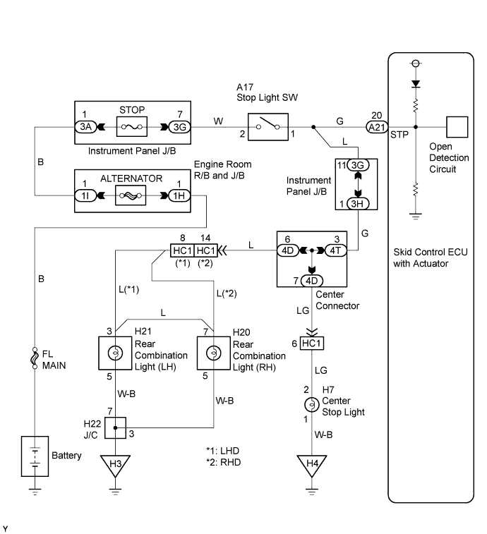
WIRING DIAGRAM
INSPECTION PROCEDURE
PROCEDURE
-
CHECK STOP LIGHT SWITCH OPERATION
-
Connect the intelligent tester II to the DLC3.
-
Turn the ignition switch to the ON position.
-
Turn the tester ON.
-
Select the DATA LIST mode on the intelligent tester II.
Select the following menu items: Chassis / ABS/VSC/TRC / Data List.
Item Measurement Item : Range (Display) Normal Conditions Stop Light SW Stop light switch : ON or OFF ON: Brake pedal applied
OFF: Brake pedal released
-
Check that "Stop Light SW" turns ON and OFF when the brake pedal is depressed and released.
OK "Stop Light SW" turns ON/OFF in accordance with operation of brake pedal.
NG 
INSPECT FUSE (STOP) Click here
OK 
-
-
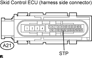
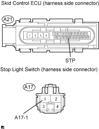
CHECK SKID CONTROL ECU TERMINAL VOLTAGE (STP)
-
Disconnect the skid control ECU connector.
-
Measure the voltage.
Standard Voltage Tester Connection Switch Condition Specified Condition A21-20 (STP) - Body ground Brake pedal depressed 8 to 14 V A21-20 (STP) - Body ground Brake pedal released Below 4.0 V
NG
CHECK HARNESS AND CONNECTOR (SKID CONTROL ECU - STOP LIGHT SWITCH) Click here
OK 
REPLACE BRAKE ACTUATOR
-
-
INSPECT FUSE (STOP)
-
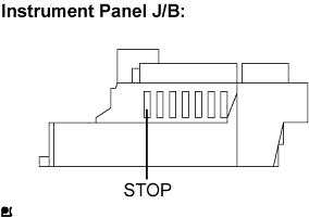
Remove the STOP fuse from the instrument panel J/B.
-
Measure the resistance.
Standard Resistance Below 1 Ω
NG 
CHECK FOR SHORT IN ALL HARNESSES AND CONNECTORS CONNECTED TO FUSE AND REPLACE FUSE
OK
-
-
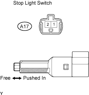
INSPECT STOP LIGHT SWITCH ASSEMBLY
-
Disconnect the stop light switch connector.
-
Measure the resistance.
Standard Resistance Switch Condition Tester Connection Specified Condition Switch pin free 1 - 2 Below 1 Ω Switch pin pushed in 1 - 2 10 kΩ or higher
NG
REPLACE STOP LIGHT SWITCH ASSEMBLY
OK
-
-
CHECK HARNESS AND CONNECTOR (SKID CONTROL ECU - STOP LIGHT SWITCH)
-
Disconnect the skid control ECU connector and stop light switch connector.
-
Measure the resistance.
Standard Resistance Tester Connection Specified Condition A21-20 (STP) - A17-1 Below 1 Ω
NG
REPAIR OR REPLACE HARNESS AND CONNECTOR
OK
-
-
RECONFIRM DTC
-
Clear the DTC Click here.
-
Check if the same DTC is recorded.
Result DTC (C1249/58) output A DTC not output B
B
END
A
REPLACE BRAKE ACTUATOR
-