ANTI-LOCK BRAKE SYSTEM, Diagnostic DTC:C1241

| DTC Code | DTC Name |
|---|---|
| C1241 | Low Power Supply Voltage Malfunction |
DESCRIPTION
If a malfunction is detected in the power supply circuit, the skid control ECU (brake actuator assembly) stores this DTC and the fail-safe function prohibits ABS operation.
This DTC is stored when the +BS terminal voltage meets one of the DTC detection conditions due to a malfunction in the power supply or charging circuit such as the battery or alternator circuit, etc.
The DTC is canceled when the +BS terminal voltage returns to normal.
| DTC No. | DTC Detection Condition | Trouble Area |
|---|---|---|
| C1241 | Any of the following is detected:
|
|
*: The skid control ECU (brake actuator assembly) monitors the resistance of the power source line at the +BS terminal. A malfunction is detected when an abnormality occurs in the +BS terminal wire harness or its connection and the skid control ECU (brake actuator assembly) determines that the wiring resistance at the +BS terminal exceeds the standard resistance.
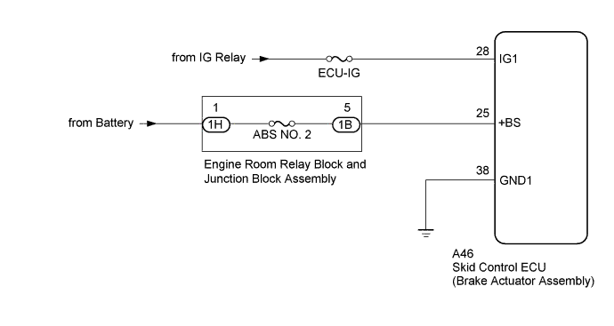
WIRING DIAGRAM
INSPECTION PROCEDURE
Note
Inspect the fuses for circuits related to this system before performing the following inspection procedure.
PROCEDURE
-
CHECK BATTERY
-
Check the battery voltage.
Standard Voltage 11 to 14 V
NG 
CHECK OR REPLACE CHARGING SYSTEM COMPONENT OR BATTERY Click here
OK 
-
-
CHECK HARNESS AND CONNECTOR (POWER SOURCE TERMINAL)
-
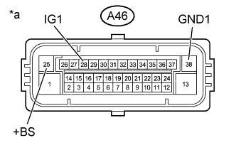
Text in Illustration *a Front view of wire harness connector
(to Skid Control ECU (Brake Actuator Assembly))
Disconnect the skid control ECU (brake actuator assembly) connector.
-
Measure the voltage according to the value(s) in the table below.
Standard Voltage Tester Connection Condition Specified Condition A46-25 (+BS) - Body ground Always 11 to 14 V A46-25 (+BS) - A46-38 (GND1) Always 11 to 14 V A46-28 (IG1) - Body ground Ignition switch ON 11 to 14 V A46-28 (IG1) - A46-38 (GND1) Ignition switch ON 11 to 14 V Result Result Proceed to OK A NG (for +BS circuit) B NG (for IG1 circuit) C
B 
CHECK HARNESS AND CONNECTOR (SKID CONTROL ECU - ENGINE ROOM RELAY BLOCK AND JUNCTION BLOCK ASSEMBLY) Click here
C
REPAIR OR REPLACE HARNESS OR CONNECTOR (IG1 CIRCUIT)
A
-
-
CHECK HARNESS AND CONNECTOR (GND1 TERMINAL)
-
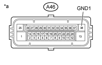
Text in Illustration *a Front view of wire harness connector
(to Skid Control ECU (Brake Actuator Assembly))
Turn the ignition switch off.
-
Measure the resistance according to the value(s) in the table below.
Standard Resistance Tester Connection Condition Specified Condition A46-38 (GND1) - Body ground Always Below 1 Ω
NG
REPAIR OR REPLACE HARNESS OR CONNECTOR (GND1 CIRCUIT)
OK
-
-
RECONFIRM DTC
-
Reconnect the skid control ECU (brake actuator assembly) connector.
-
Clear the DTCs Click here.
-
Turn the ignition switch off.
-
Start the engine.
-
Perform a road test.
-
Check if the same DTC is output Click here.
Result Result Proceed to DTC C1241 is not output. A DTC C1241 is output. B Tech Tips
If troubleshooting has been carried out according to Problem Symptoms Table, refer back to the table and proceed to the next step before replacing parts Click here.
B
REPLACE BRAKE ACTUATOR ASSEMBLY Click here
A 
CHECK FOR INTERMITTENT PROBLEMS
-
-
CHECK HARNESS AND CONNECTOR (SKID CONTROL ECU - ENGINE ROOM RELAY BLOCK AND JUNCTION BLOCK ASSEMBLY)
-
Turn the ignition switch off.
-
Disconnect the 1B engine room relay block and junction block assembly connector.
-
Measure the resistance according to the value(s) in the table below.
Standard Resistance Tester Connection Condition Specified Condition A46-25 (+BS) - 1B-5 Always Below 1 Ω Tech Tips
-
Even if the resistance between the skid control ECU (brake actuator assembly) and the engine room relay block and junction block assembly is normal, there may be an abnormality in the resistance of the wiring between the battery and the engine room relay block and junction block assembly. Therefore, be sure to inspect the circuit between the battery and the engine room relay block and junction block assembly before replacing the skid control ECU (brake actuator assembly).
-
If troubleshooting has been carried out according to Problem Symptoms Table, refer back to the table and proceed to the next step before replacing parts Click here.
-
NG
REPAIR OR REPLACE WIRE HARNESS OR ENGINE ROOM RELAY BLOCK AND JUNCTION BLOCK ASSEMBLY
OK
REPLACE BRAKE ACTUATOR ASSEMBLY Click here
-