ANTI-LOCK BRAKE SYSTEM, Diagnostic DTC:C1241/41

| DTC Code | DTC Name |
|---|---|
| C1241/41 | Low Battery Positive Voltage or Abnormally High Battery Positive Voltage |
DESCRIPTION
When there is an abnormality in the power supply circuit of the brake actuator (skid control ECU), the skid control ECU sets a DTC and the operation is prohibited by the fail-safe function. This DTC is set when the voltage supplied to terminal IG1 is outside DTC detection thresholds, due to abnormalities of the battery, power source circuits or charging circuits such as the alternator circuit.
Fail-safe function is canceled when the voltage to terminal IG1 returns to normal.
| DTC No. | DTC Detecting Conditions | Trouble Areas |
|---|---|---|
| C1241/41 | When either of following (1 or 2) detected: 1. At vehicle speed of 6 km/h (4 mph) or more, terminal IG1 voltage 9.6 V or less when no ABS control, or 9.3 V or less during ABS control. 2. Terminal IG voltage 16.9 V or more. |
|
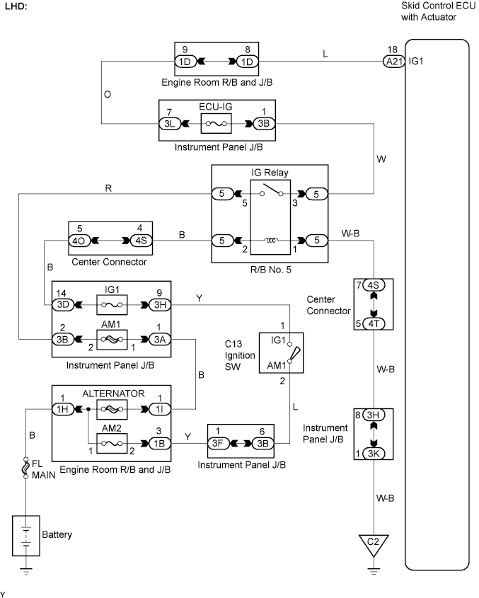
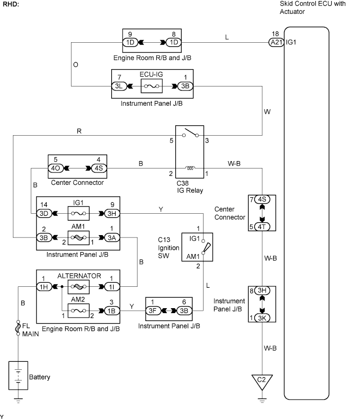
WIRING DIAGRAM
INSPECTION PROCEDURE
PROCEDURE
-
INSPECT SKID CONTROL ECU TERMINAL VOLTAGE
-
When using an intelligent tester:
-
Connect the intelligent tester to the DLC3.
-
Start the engine.
-
Turn the tester ON.
-
Read the value using the intelligent tester.
Select the following menu items: Chassis / ABS/VSC/TRC / Data List.
Item Measurement Item : Range (Display) Normal Condition ECU IG Power Voltage ECU power supply voltage : TOO LOW / NORMAL / TOO HIGH TOO HIGH: 14.0 V or more
NORMAL: 9.5 to 14.0 V
TOO LOW: Below 9.5 V
OK "Normal" is displayed.
-
-
When not using an intelligent tester:
-
Disconnect the skid control ECU connector.
-
Turn the ignition switch to the ON position.
-
Measure the voltage.
Standard Voltage Tester Connection Specified Condition A21-18 (IG1) - Body ground 10 to 14 V
-
NG 
REPAIR OR REPLACE HARNESS AND CONNECTOR
OK 
-
-
INSPECT FUSE (ECU-IG)
-
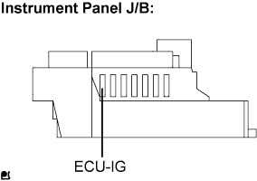
Remove the ECU-IG fuse from the instrument panel J/B.
-
Measure the resistance.
Standard Resistance Below 1 Ω
NG
CHECK FOR SHORT IN ALL HARNESSES AND CONNECTORS CONNECTED TO FUSE AND REPLACE FUSE
OK
-
-
INSPECT BATTERY
-
Check the battery voltage.
Standard Voltage 11 to 14 V
NG
CHECK CHARGING SYSTEM
OK
-
-
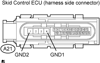
CHECK HARNESS AND CONNECTOR (SKID CONTROL ECU - BODY GROUND)
-
Inspect the skid control ECU connector fitting for any defects.
-
Disconnect the skid control ECU connector.
-
Inspect both the connector case and the terminal for deformation and corrosion.
OK No deformation or corrosion. -
Measure the resistance.
Standard Resistance Tester Connection Specified Condition A21-4 (GND1) - Body ground Below 1 Ω A21-1 (GND2) - Body ground Below 1 Ω
NG
REPAIR OR REPLACE HARNESS AND CONNECTOR
OK
-
-
RECONFIRM DTC
-
Clear the DTC Click here.
-
Drive the vehicle at 6 km/h (4 mph) or more for several seconds.
-
Check if the same DTC is output.
Result DTC output A DTC not output B
B
END
A 
REPLACE BRAKE ACTUATOR
-