ANTI-LOCK BRAKE SYSTEM, Diagnostic DTC:C1237/37

| DTC Code | DTC Name |
|---|---|
| C1237/37 | Speed Sensor Rotor is Wrong Number of Teeth on One of the 4 Wheels |
DESCRIPTION
This DTC is set when there is a tire size abnormality or when foreign matter is attached to the speed sensor tip or the sensor rotor.
The skid control ECU determines whether foreign matter is present, through the pulse signals transmitted by the sensor.
This DTC may be set due to defects in the connector terminal or wire harness of the speed sensor circuit.
| DTC No. | DTC Detecting Conditions | Trouble Areas |
|---|---|---|
| C1237/37 | When any of following (1 to 3) detected: 1. Discrepancy among four wheel speed sensor output. 2. Abnormal pulse signals from 3 or more sensors. 3. Continuous ABS control for 60 seconds or more. |
|
Tech Tips
C1237/37: The skid control ECU begins to detect this DTC when the vehicle speed exceeds 100 km/h (62 mph).
INSPECTION PROCEDURE
PROCEDURE
-
INSPECT TIRES
-
Check the tire sizes and conditions of each wheel.
OK All 4 wheels are the same size and in the same condition.
NG 
REPLACE TIRES SO THAT ALL 4 TIRES ARE SAME SIZE
OK 
-
-
CHECK SPEED SENSOR ROTOR
-
Remove the front drive shaft.
-
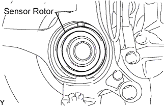
Check the sensor rotor.
OK No scratches or foreign matter on the sensor rotor.
NG
CLEAN FRONT SPEED SENSOR ROTOR OR REPLACE FRONT AXLE HUB BEARING
OK
-
-
CHECK SPEED SENSOR
-
Remove the front speed sensor and the rear speed sensor.
-
Check the sensor tips.
OK No scratches or foreign matter on the sensor tip.
NG
REPLACE FRONT SPEED SENSOR OR REAR SPEED SENSOR
OK
-
-
CHECK HARNESS AND CONNECTOR (SKID CONTROL ECU - SPEED SENSOR)
-
Inspect the skid control ECU connector fitting for any defects.
-
Disconnect the skid control ECU connector and the speed sensor connector.
-
Inspect both the connector case and the terminal for deformation and corrosion.
OK No deformation or corrosion. -
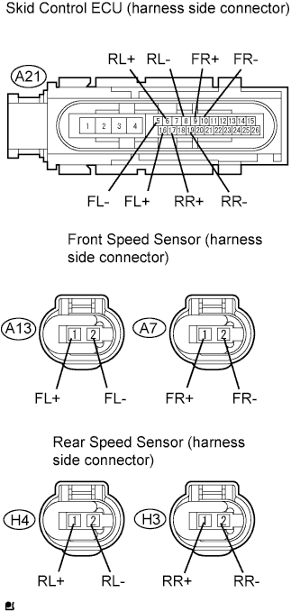
Measure the resistance.
Standard Resistance Tester Connection Specified Condition A21-16 (FL+) - A13- 1 (FL+) Below 1 Ω A21-5 (FL-) - A13-2 (FL-) Below 1 Ω A21-9 (FR+) - A7-1 (FR+) Below 1 Ω A21-10 (FR-) - A7-2 (FR-) Below 1 Ω A21-6 (RL+) - H4-1 (RL+) Below 1 Ω A21-8 (RL-) - H4-2 (RL-) Below 1 Ω A21-17 (RR+) - H3-1 (RR+) Below 1 Ω A21-19 (RR-) - H3-2 (RR-) Below 1 Ω Standard Resistance Tester Connection Specified Condition A13-1 (FL+) - Body ground 10 kΩ or higher A13-2(FL-) - Body ground 10 kΩ or higher A7-1 (FR+) - Body ground 10 kΩ or higher A7-2(FR-) - Body ground 10 kΩ or higher H4-1 (RL+) - Body ground 10 kΩ or higher H4-2 (RL-) - Body ground 10 kΩ or higher H3-1 (RL+) - Body ground 10 kΩ or higher H3-2 (RL-) - Body ground 10 kΩ or higher
NG
REPAIR OR REPLACE HARNESS AND CONNECTOR
OK 
REPLACE BRAKE ACTUATOR
-