ANTI-LOCK BRAKE SYSTEM, Diagnostic DTC:C0200/31, C0205/32, C1271/71, C1272/72, C1275/75, C1276/76, C1330/35, C1331/36

| DTC Code | DTC Name |
|---|---|
| C0200/31 | Right Front Wheel Speed Sensor Signal |
| C0205/32 | Left Front Wheel Speed Sensor Signal |
| C1271/71 | Low Output Signal of Front Speed Sensor RH (Test Mode DTC) |
| C1272/72 | Low Output Signal of Front Speed Sensor LH (Test Mode DTC) |
| C1275/75 | Abnormal Change in Output Signal of Front Speed Sensor RH (Test Mode DTC) |
| C1276/76 | Abnormal Change in Output Signal of Front Speed Sensor LH (Test Mode DTC) |
| C1330/35 | Open Circuit in Right Front Wheel Speed Sensor Circuit |
| C1331/36 | Open Circuit in Left Front Wheel Speed Sensor Circuit |
DESCRIPTION
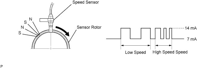
The speed sensors detect the wheel speeds and send appropriate signals to the skid control ECU.
Speed sensor rotors have rows of alternating N and S magnetic poles, and their magnetic fields change when the rotors turn.
Each speed sensor detects that magnetic change and sends a pulse signal to the skid control ECU. The ECU monitors the wheel speeds through these pulse signals to control the ABS control system.
| DTC No. | DTC Detecting Conditions | Trouble Areas |
|---|---|---|
| C0200/31 C0205/32 |
When either of following (1 or 2) detected: 1. Even during normal driving the speed signal indicates rapid acceleration/deceleration for 20 seconds or more with brake pedal depressed, or for 5 seconds or more without the brake pedal depressed. 2. Wheel speed of 0 km/h detected when vehicle speed has reached 12 km/h (7 mph) after starting vehicle. |
|
| C1271/71 C1272/72 |
These DTCs detected only during test mode. |
|
| C1275/75 C1276/76 |
These DTCs detected only during test mode. |
|
| C1330/35 C1331/36 |
Abnormality detected in resistance value of each speed sensor. |
|
Tech Tips
-
DTCs C0200/31 and C1330/35 relate to the front speed sensor RH.
-
DTCs C0205/32 and C1331/36 relate to the front speed sensor LH.
-
C0200/31, C0205/32: The skid control ECU monitors the malfunctions when the vehicle has been driven at 20 km/h (12 mph) or more for at least 30 seconds.
-
C1330/35, C1331/36: The skid control ECU completes the malfunction monitoring process when the vehicle speed exceeds 20 km/h (12 mph).
When DTC C0200/31 or C0205/32 has been set, DTCs C1330/35 and C1331/36 are not indicated even if an open malfunction has been detected in the corresponding speed sensor circuit. Therefore, it is necessary for DTC C0200/31 and C0205/32 to be cleared from the skid control ECU to check whether DTCs C1330/35 or C1331/36 have been set. In order to check for those DTCs, conduct the following procedures before driving the vehicle:
-
Clear stored DTCs using an intelligent tester.
-
Turn the ignition switch off and then on again.
-
Start the engine.
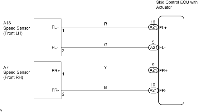
WIRING DIAGRAM
INSPECTION PROCEDURE
Tech Tips
Start the inspection from step 3 when only DTCs C1330/35 and/or C1331/36 are detected.
Note
Check the speed sensor signal in test mode after cleaning or replacement Click here.
PROCEDURE
-
READ VALUE OF INTELLIGENT TESTER (FRONT SPEED SENSOR)
-
Connect the intelligent tester to the DLC3.
-
Start the engine and drive the vehicle.
-
Turn the tester ON.
-
Read the wheel speed value using the intelligent tester.
Select the following menu items: Chassis / ABS/VSC/TRC / Data List.
-
Select the item "FR (FL) Wheel Speed" in the DATA LIST and read the value displayed on the intelligent tester.
Item Measurement Item : Range (Display) Normal Condition FR Wheel Speed Wheel speed sensor (FR) reading : min.: 0 km/h (0 MPH), max.: 326 km/h (202 MPH) Similar to speed indicated on speedometer FL Wheel Speed Wheel speed sensor (FR) reading : min.: 0 km/h (0 MPH), max.: 326 km/h (202 MPH) Similar to speed indicated on speedometer -
Check that there is no significant difference between the speed value output from the speed sensor displayed on the intelligent tester and the speed value displayed on the speedometer when driving the vehicle.
OK There is almost no difference in the displayed speed values. Tech Tips
There is a tolerance of +- 10% in the speedometer indication.
OK 
TEST MODE INSPECTION Click here
NG 
-
-
CHECK SENSOR INSTALLATION
-
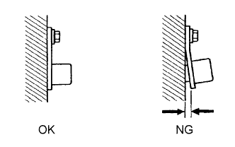
Check the speed sensor installation.
OK The installation bolt is tightened properly. There is no clearance between the sensor and front steering knuckle. - Torque:
- 8.0 N*m { 82 kgf*cm, 71 in.*lbf }
Tech Tips
If the installation portion of the sensor is dirty, clean it and reinstall the sensor.
NG 
TIGHTEN BOLT PROPERLY OR REPLACE FRONT SPEED SENSOR
OK
-
-
CHECK FRONT SPEED SENSOR
-
Inspect the front speed sensor connector fitting for any defects such as looseness and detachment.
-
Disconnect the front speed sensor connector.
-
Inspect both the connector case and the terminal for deformation and corrosion.
OK No deformation or corrosion.
NG
REPLACE FRONT SPEED SENSOR
OK
-
-
CHECK HARNESS AND CONNECTOR (SKID CONTROL ECU - FRONT SPEED SENSOR)
-
Confirm that the skid control ECU connector and speed sensor connector are properly connected.
-
Disconnect the skid control ECU connector and the front speed sensor connector.
-
Inspect both the connector case and the terminal for deformation and corrosion.
OK No deformation or corrosion. -
Measure the resistance.
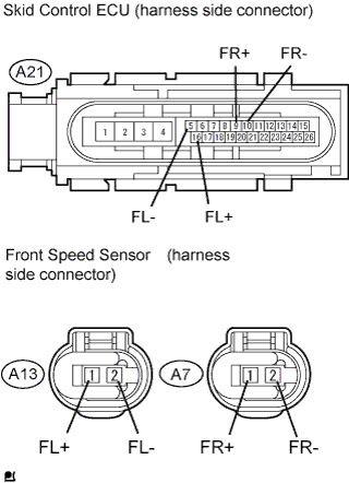
Standard Resistance (LH) Tester Connection Specified Condition A21-16 (FL+) - A13-1 (FL+) Below 1 Ω A21-5 (FL-) - A13-2 (FL-) Below 1 Ω Standard Resistance (RH) Tester Connection Specified Condition A21-9 (FR+) - A7-1 (FR+) Below 1 Ω A21-10 (FR-) - A7-2 (FR-) Below 1 Ω
NG
REPAIR OR REPLACE HARNESS AND CONNECTOR
OK
-
-
CHECK SPEED SENSOR TIP
-
Remove the speed sensor Click here.
-
Check the sensor tip.
OK No scratches or foreign matter on the sensor tip.
NG
CLEAN OR REPLACE SPEED SENSOR
OK
-
-
CHECK SPEED SENSOR ROTOR
-
Remove the front drive shaft.
-
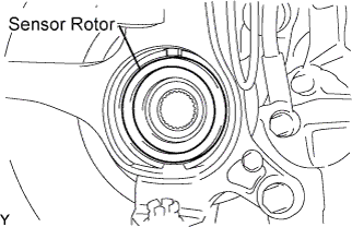
Check the speed sensor rotor.
OK No scratches or foreign matter on the sensor rotor.
NG
CLEAN SPEED SENSOR ROTOR OR REPLACE FRONT AXLE HUB BEARING
OK
-
-
TEST MODE INSPECTION
-
Perform a TEST MODE inspection and a check for DTCs Click here.
OK No DTC output.
NG
REPLACE FRONT SPEED SENSOR
OK 
CHECK FOR INTERMITTENT PROBLEMS
-
-
TEST MODE INSPECTION
-
Perform a TEST MODE inspection and a check for DTCs Click here.
OK No DTC output.
NG
REPLACE BRAKE ACTUATOR
OK
CHECK FOR INTERMITTENT PROBLEMS
-