ANTI-LOCK BRAKE SYSTEM TEST MODE PROCEDURE

Tech Tips
-
By switching the skid control ECU from normal mode to test mode, abnormal detection sensitivity is enhanced and troubleshooting can be conducted efficiently.
-
Perform a sensor check in test mode after the speed sensor or sensor rotor has been repaired or replaced.
-
SPEED SENSOR SIGNAL CHECK (USING INTELLIGENT TESTER)
Tech Tips
If the ignition switch is turned from the ON to the ACC or LOCK position during test mode, DTCs related to the signal check function are erased.
-
Procedures for test mode:
-
Turn the ignition switch to OFF.
-
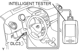
Connect the intelligent tester to the DLC3.
-
Start the engine.
-
Switch the skid control ECU to test mode using the intelligent tester.
Select the following menu items: Chassis / ABS/VSC/TRC / Utility / Signal Check.
-
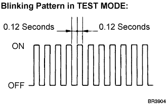
Check that the ABS warning light blinks as shown in the illustration.
Tech Tips
If the ABS warning light does not blink, inspect the ABS warning light circuit.
Trouble area See page ABS warning light circuit
-
-
Check the speed sensor signal.
-
Drive the vehicle straight forward at a speed of 55 km/h (34 mph) or more for several seconds, then step on the brake pedal.
-
Check that the ABS warning light goes off.
Tech Tips
-
The sensor check may not be completed if the vehicle has its wheel spun or its steering wheel turned during this check.
-
If the steering wheel is turned during the speed sensor check, the ABS warning light may go on after the low speed check is finished.
-
The ABS warning light goes on immediately when an abnormality is detected.
-
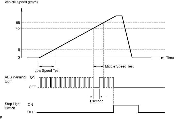
The ABS warning light turns off for 1 second when the middle speed test is started.
-
When the speed sensor signal is normal, the ABS warning light operates as shown in the illustration below.
-
-
Stop the vehicle.
-
Read the DTCs.
Tech Tips
See the list of DTCs shown in step 3.
-
-
-
SPEED SENSOR CHECK (USING SST CHECK WIRE)
Tech Tips
If the ignition switch is turned from the ON to the ACC or LOCK position during test mode, DTCs related to the signal check function are erased.
-
Procedures for test mode:
-
Turn the ignition switch to OFF.
-
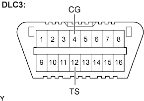
Using SST, connect terminals TS and CG of the DLC3.
- SST
- 09843-18040
-
Turn the ignition switch to the ON position.
-
Check that the ABS warning light blinks as shown in the illustration.
Tech Tips
If the ABS warning light does not blink, inspect the ABS warning light circuit and the TS terminal circuit.
Trouble area See page ABS warning light circuit TS terminal circuit
-
-
Check the speed sensor signal.
-
Drive the vehicle straight forward at a speed of 55km/h (34 mph) or more for several seconds and then step on the brake pedal.
-
Check that the ABS warning light goes off.
Tech Tips
-
The sensor check may not be completed if the vehicle has its wheel spun or its steering wheel turned during this check.
-
If the speed sensor check is commenced while the steering wheel is turned, the ABS warning light may go on after the low speed check is finished.
-
The ABS warning light goes on immediately when an abnormality is detected.
-
The ABS warning light turns off for 1 second when the middle speed test is started.
-
When the speed sensor signal is normal, the ABS warning light operates as shown in the illustration below.
-
-
Stop the vehicle.
-
Turn the ignition switch to OFF.
-
Disconnect the SST from terminal TS.
-
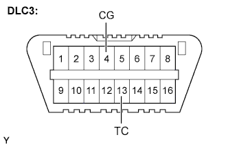
Using SST, connect terminals TC and CG of the DLC3.
- SST
- 09843-18040
Tech Tips
If both TC and TS are connected to CG, TEST MODE is activated and DTCs are not output.
-
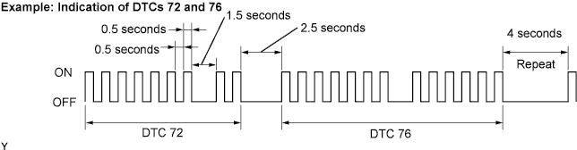
Read the number of blinks of the ABS warning light.
Tech Tips
-
See the list of DTCs shown in step 3.
-
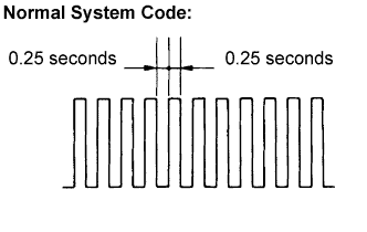
If every sensor is normal, a normal system code is output (a cycle of 0.25 seconds ON and 0.25 seconds OFF is repeated).
-
If 2 or more malfunctions are indicated at the same time, the lowest numbered code is displayed first.
-
-
After performing the check, turn the ignition switch to off, and remove the SST from the DLC3.
- SST
- 09843-18040
-
-
-
SPEED SENSOR CHECK FUNCTION DTCs
Code No. Diagnosis Trouble Areas C1271/71 Low output signal of front speed sensor RH
-
Front speed sensor RH
-
Speed sensor circuit
-
Sensor installation
C1272/72 Low output signal of front speed sensor LH
-
Front speed sensor LH
-
Speed sensor circuit
-
Sensor installation
C1273/73 Low output signal of rear speed sensor RH
-
Rear speed sensor RH
-
Speed sensor circuit
-
Sensor installation
C1274/74 Low output signal of rear speed sensor LH
-
Rear speed sensor LH
-
Speed sensor circuit
-
Sensor installation
C1275/75 Abnormal change in output signal of front speed sensor RH
-
Sensor installation
-
Speed sensor rotor
-
Foreign matter on sensor tip or sensor rotor
C1276/76 Abnormal change in output signal of front speed sensor LH
-
Sensor installation
-
Speed sensor rotor
-
Foreign matter on sensor tip or sensor rotor
C1277/77 Abnormal change in output signal of rear speed sensor RH
-
Sensor installation
-
Speed sensor rotor
-
Foreign matter on sensor tip or sensor rotor
C1278/78 Abnormal change in output signal of rear speed sensor LH
-
Sensor installation
-
Speed sensor rotor
-
Foreign matter on sensor tip or sensor rotor
Tech Tips
-
The codes in this table are only output in TEST MODE.
-
Detection of DTCs from C1271/71 to C1274/74 is completed before the vehicle speed reaches 5 km/h (3 mph).
-
Detection of DTCs from C1275/75 to C1278/78 is completed before the vehicle speed reaches 55 km/h (34 mph).
-
C1271/71 - C1274/74: Speed output from only one wheel is extremely low despite the other wheel speed outputs reaching 4 km/h (3 mph).
-
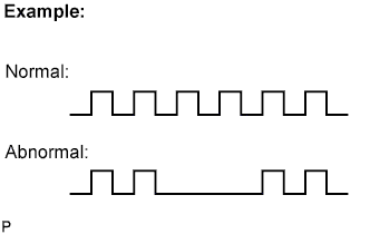
C1275/75 - C1278/78: Abnormal speed sensor output frequency is as shown in the illustration.
-