FRONT SHOCK ABSORBER WITH COIL SPRING INSTALLATION

-
INSTALL FRONT SHOCK ABSORBER WITH COIL SPRING
-
Install the nut through front suspension support No. 2.
-
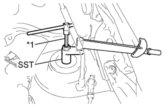
Text in Illustration *1 Long Socket Hexagon Wrench 6 Using SST and a long socket hexagon wrench 6, fix the shock absorber rod and tighten the nut.
- SST
- 09729-97202
- Torque:
- without SST
- 55 N*m { 561 kgf*cm, 41 ft.*lbf }
- with SST
- 49 N*m { 495 kgf*cm, 36 ft.*lbf }
Tech Tips
-
This torque value is effective when SST is parallel to the torque wrench.
-
This torque value can be obtained by using a torque wrench with a fulcrum length of 300 mm (11.8 in.) and SST with a fulcrum length of 40 mm (1.57 in.).
-
If using a torque wrench with a length that is not 300 mm (11.8 in.), calculate the torque specification for the torque wrench and SST based on the "without SST" torque specification Click here.
-
-
INSTALL STEERING KNUCKLE
-
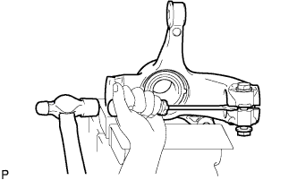
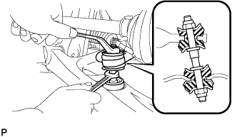
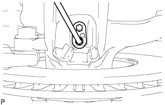
Fix the steering knuckle in a vise and provisionally install the bolt and nut. Then, using a screwdriver and hammer, widen the knuckle slit.
Note
-
Do not widen the steering knuckle slit by more than 10 mm.
-
Do not damage the steering knuckle slit portion.
-
-
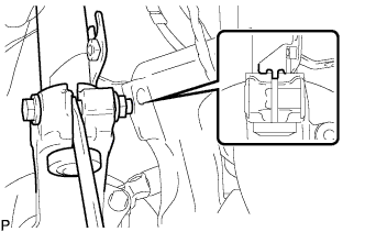
Insert the convex portion of the shock absorber into the steering knuckle slit. In addition, make the bracket edge come into contact with the steering knuckle tip.
Note
Set the nut on the front side of the vehicle.
-

Release the screwdriver. Then tighten the nut to tighten the shock absorber steering knuckle.
- Torque:
- 52 N*m { 530 kgf*cm, 38 ft.*lbf }
-
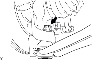
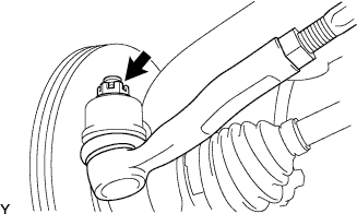
Remove any materials such as iron powder that adhere to the magnetic seal portion.
-
-
INSTALL FRONT AXLE ASSEMBLY
-
Push the front axle assembly out of the vehicle to align the spline of the front drive shaft assembly with the front axle assembly and insert the front axle assembly.
Note
-
Do not push the front axle assembly further out of the vehicle than is necessary.
-
Do not damage the oil seal.
-
Do not damage the front drive shaft assembly boot.
-
Do not damage the speed sensor rotor.
-
Check for any foreign matter on the speed sensor rotor and insertion part.
-
-
-
INSTALL FRONT SUSPENSION LOWER ARM
-
Push the front suspension lower arm No. 1 downward, install the front lower ball joint and tighten the castle nut and a new clip.
- Torque:
- 98 N*m { 1,000 kgf*cm, 72 ft.*lbf }
Note
Retighten the castle nut and clip within a turning angle of 60° after aligning the hole of the clip with the castle nut.
-
-
INSTALL FRONT STABILIZER BAR
-
Install the stabilizer bar front with the 2 cushion retainers, 2 cushions and a nut, as shown in the illustration.
Note
Be sure to install the cushion and retainer in the correct direction.
-
Tighten the nut with a spanner (10 mm).
- Torque:
- 18 N*m { 184 kgf*cm, 13 ft.*lbf }
-
-
INSTALL TIE ROD END SUB-ASSEMBLY
-
Connect the tie rod end to the steering knuckle and install it with the castle nut and a new cotter pin.
- Torque:
- 33 N*m { 336 kgf*cm, 24 ft.*lbf }
Note
Retighten the castle nut and cotter pin within a turning angle of 60° after aligning the hole of the cotter pin with the castle nut.
-
-
INSTALL FRONT DISC BRAKE CALIPER ASSEMBLY
-
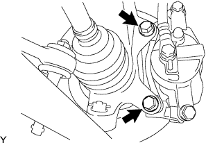
Install the front disc brake caliper assembly onto the steering knuckle with the 2 bolts.
- Torque:
- 88 N*m { 900 kgf*cm, 65 ft.*lbf }
-
Install the flexible hose onto the shock absorber assembly with the bolt.
- Torque:
- 29 N*m { 300 kgf*cm, 22 ft.*lbf }
-
-
INSTALL FRONT SPEED SENSOR
-
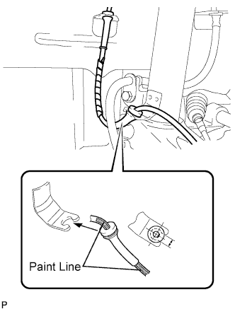
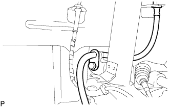
Connect the speed sensor wire to the shock absorber assembly.
Note
Insert a rubber grommet into the bracket with the painted line placed between the bracket cutouts.
-
Install the bolt and speed sensor front onto the steering knuckle.
- Torque:
- 8.0 N*m { 82 kgf*cm, 71 in.*lbf }
Note
-
Do not damage the speed sensor.
-
Keep the speed sensor free of any foreign material.
-
Do not twist the sensor wire when installing the speed sensor.
-
-
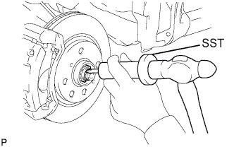
INSTALL FRONT AXLE HUB NUT
-
Install a new front axle hub nut.
- Torque:
- 216 N*m { 2,202 kgf*cm, 160 ft.*lbf }
-
Using a hammer and chisel, stake the front axle hub nut.
-
-
INSTALL FRONT WHEEL
- Torque:
- 103 N*m { 1050 kgf*cm, 76 ft.*lbf }
-
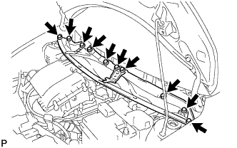
INSTALL COWL TOP PANEL OUTER
-
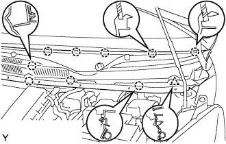
Install the cowl top panel with the 10 bolts.
- Torque:
- 9.2 N*m { 94 kgf*cm, 81 in.*lbf }
-
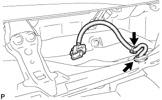
Install the grommet of the wire harness.
-
Install the clamp of the wire harness.
-
-
INSTALL FRONT WIPER MOTOR AND LINK ASSEMBLY
-
Connect the connector.
-
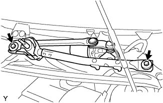
Install the front wiper motor and link assembly with the 2 bolts.
- Torque:
- 13 N*m { 127 kgf*cm, 9 ft.*lbf }
-
-
INSTALL COWL TOP VENTILATOR LOUVER RH
-
Connect the washer hose.
-

Engage the 8 claws and install the cowl top ventilator louver RH.
-
Install the clip.
-
-
INSTALL COWL TOP VENTILATOR LOUVER LH
-
Connect the washer hose.
-
Engage the 9 claws and install the cowl top ventilator louver LH.
-
Install the clip.
-
-
INSTALL HOOD TO COWL TOP SEAL

-
Engage the 8 clips and install the hood to cowl top seal.
-
-
INSTALL FRONT WIPER ARM
-
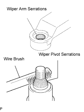
Scrape any metal powder off the serrated part of the wiper arm with a round file or equivalent (when reinstalling).
-
Clean the wiper pivot serrations with a wire brush.
-
Operate the wiper, then stop the windshield wiper motor assembly in the automatic stop position.
-
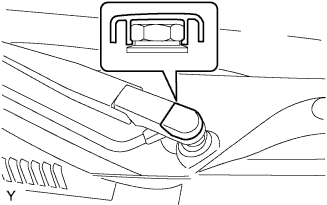
Provisionally install the front wiper main arm with the nut.
-
Install the front wiper secondary arm onto the front wiper motor and link assembly.
-
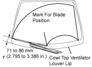
Align the blade tip with the mark on the windshield glass, as shown in the illustration.
-
Tighten the nut of the front wiper main arm.
- Torque:
- 21 N*m { 209 kgf*cm, 15 ft.*lbf }
-
-
INSTALL FRONT WIPER ARM HEAD CAP
-
Engage the claw and install the front wiper arm head cap.
-
-
CONNECT CABLE TO NEGATIVE BATTERY TERMINAL
- Torque:
- 5.4 N*m { 55 kgf*cm, 48 in.*lbf }
-
CHECK ABS SENSOR SIGNAL (w/o VSC)
-
CHECK VSC SENSOR SIGNAL (w/ VSC)
-
INSPECT FRONT WHEEL ALIGNMENT