REAR AXLE BEAM INSTALLATION

-
TEMPORARILY TIGHTEN REAR AXLE BEAM ASSEMBLY
-
Support the rear axle beam with a jack.
-
Install the rear axle beam onto the vehicle and provisionally tighten the 2 bolts.
-
-
INSTALL REAR COIL SPRING LH
-
Install the coil spring insulator lower onto the rear axle beam.
-
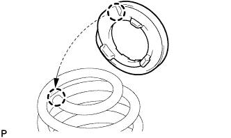
Install the coil spring insulator upper so that its gap fits onto the end of coil spring.
-
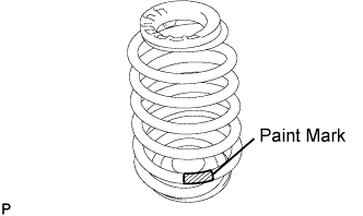
Install the coil spring onto the rear axle beam.
Note
The paint mark of the coil spring should be on the underside and rearside of the vehicle.
-
-
INSTALL REAR COIL SPRING RH
Tech Tips
The installation procedure for the RH side is the same as that for the LH side.
-
TEMPORARILY TIGHTEN SHOCK ABSORBER ASSEMBLY REAR LH
-
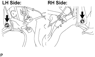
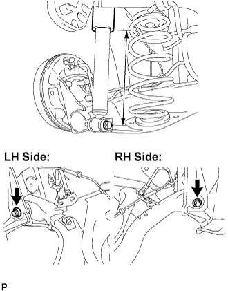
Jack up the the rear axle beam slowly, and install the shock absorber (lower side) onto the rear axle beam.
-
Provisionally tighten the bolt.
-
-
TEMPORARILY TIGHTEN SHOCK ABSORBER ASSEMBLY REAR RH
Tech Tips
The installation procedure for the RH side is the same as that for the LH side.
-
INSTALL REAR AXLE HUB AND BEARING ASSEMBLY LH
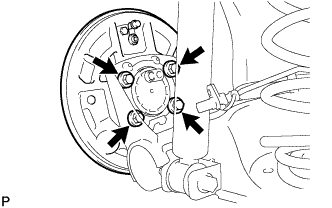
-
Install the backing plate and rear axle hub and bearing onto the rear axle beam with the 4 bolts.
- Torque:
- 60 N*m { 612 kgf*cm, 44 ft.*lbf }
-
-
INSTALL REAR AXLE HUB AND BEARING ASSEMBLY RH
Tech Tips
The installation procedure for the RH side is the same as that for the LH side.
-
INSTALL PARKING BRAKE CABLE ASSEMBLY NO.3
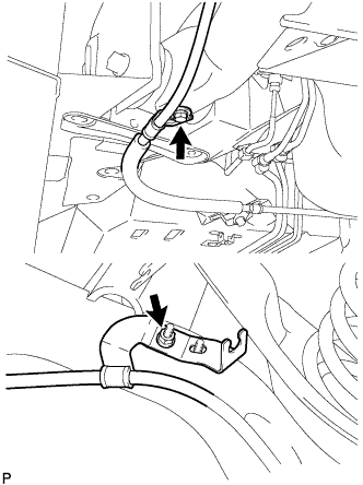
-
Install the parking brake cable with the bolt and nut.
- Torque:
- 6.0 N*m { 61 kgf*cm, 53 in.*lbf }
-
-
INSTALL PARKING BRAKE CABLE ASSEMBLY NO.2
Tech Tips
The installation procedure for the RH side is the same as that for the LH side.
-
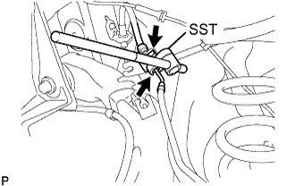
INSTALL REAR BRAKE TUBE NO.4
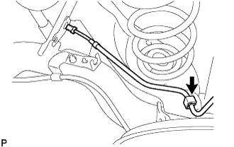
-
Install the new brake tube clamp onto the rear axle beam.
-
Install the brake tube onto the brake tube clamp.
-
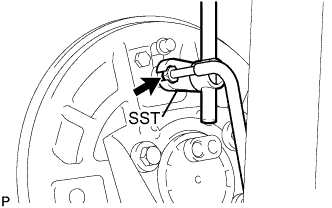
Using SST, install the brake tube.
- SST
- 09023-00101
- Torque:
- 15.2 N*m { 155 kgf*cm, 11 ft.*lbf }
-
-
INSTALL REAR BRAKE TUBE NO.3
Tech Tips
The installation procedure for the RH side is the same as that for the LH side.
-
CONNECT REAR LH FLEXIBLE HOSE
-
Connect the flexible hose to the rear axle beam with a new clip.
-
Using SST, install the brake tube.
- SST
- 09023-00101
- Torque:
- 15.2 N*m { 155 kgf*cm, 11 ft.*lbf }
-
-
CONNECT REAR RH FLEXIBLE HOSE
Tech Tips
The installation procedure for the RH side is the same as that for the LH side.
-
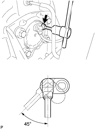
INSTALL REAR SPEED SENSOR
-
Using "Torx" socket wrench T30, install the speed sensor with the screw.
- Torque:
- 8.0 N*m { 82 kgf*cm, 71 in.*lbf }
Note
When turning the speed sensor to insert it, the turning angle should be less than 45° to avoid damaging the O-ring.
Tech Tips
If the installation portion of the sensor is dirty, clean it and reinstall the sensor.
-
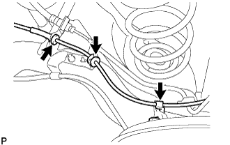
Connect the 3 clamps.
Tech Tips
The installation procedure for the RH side is the same as that for the LH side.
-
-
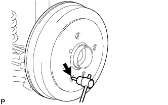
INSTALL REAR BRAKE DRUM
-
Using "Torx" socket wrench T30, install the rear brake drum with the screw.
- Torque:
- 5.0 N*m { 51 kgf*cm, 44 in.*lbf }
-
-
FULLY TIGHTEN REAR AXLE BEAM ASSEMBLY
-
Stabilize the suspension.
If it is impossible to tighten the bolt in this position, support the rear axle spring seat with a jack.
Length of shock absorber 230 mm (9.1 in.) -
Fully tighten the 2 bolts.
- Torque:
- 123 N*m { 1,255 kgf*cm, 91 ft.*lbf }
-
-
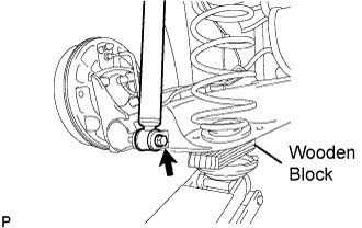
FULLY TIGHTEN SHOCK ABSORBER ASSEMBLY REAR LH
-
Fully tighten the bolt.
- Torque:
- 48 N*m { 489 kgf*cm, 35 ft.*lbf }
-
-
FULLY TIGHTEN SHOCK ABSORBER ASSEMBLY REAR RH
Tech Tips
The installation procedure for the RH side is the same as that for the LH side.
-
FILL RESERVOIR WITH BRAKE FLUID
Fluid SAE J1704 or FMVSS No. 116 DOT4 -
BLEED BRAKE MASTER CYLINDER
Tech Tips
If the master cylinder has been disassembled or if the reservoir becomes empty, bleed the air from the master cylinder.
-
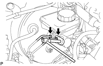
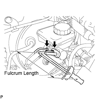
Using a 10 mm union nut wrench, separate the brake tubes from the master cylinder (w/o VSC).
-
Using a 12 mm union nut wrench, separate the brake tubes from the master cylinder (w/ VSC).
-
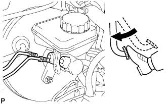
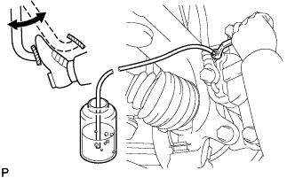
Slowly depress the brake pedal and hold it there (Step A).
-
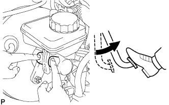
Block the outer holes with your fingers, and release the brake pedal (Step B).
-
Repeat step A and B 3 or 4 times.
-
Using a 10 mm union nut wrench, install the brake tubes to the master cylinder (w/o VSC).
- Torque:
- without 10 mm union nut wrench
- 15 N*m { 155 kgf*cm, 11 ft.*lbf }
- with 10 mm union nut wrench
- 14 N*m { 143 kgf*cm, 10 ft.*lbf }
Note
-
This torque value can be obtained by using a torque wrench with a fulcrum length of 300 mm (11.8 in.) and a 10 mm union nut wrench with a fulcrum length of 22 mm (0.886 in.) Click here.
-
This torque value is effective when the union nut wrench is parallel to a torque wrench.
-
Using a 12 mm union nut wrench, install the brake tubes to the master cylinder (w/ VSC).
- Torque:
- without 12 mm union nut wrench
- 20 N*m { 204 kgf*cm, 15 ft.*lbf }
- with 12 mm union nut wrench
- 18 N*m { 184 kgf*cm, 13 ft.*lbf }
Note
-
This torque value can be obtained by using a torque wrench with a fulcrum length of 300 mm (11.8 in.) and a 12 mm union nut wrench with a fulcrum length of 30 mm (1.18 in.) Click here.
-
This torque value is effective when the union nut wrench is parallel to a torque wrench.
-
-
BLEED BRAKE LINE
-
Connect a vinyl tube to the bleeder plug.
-
Depress the brake pedal several times, then loosen the bleeder plug with the pedal depressed (Step C).
-
At the point where the fluid stops coming out, tighten the bleeder plug, then release the brake pedal (Step D).
-
Repeat step C and D until all the air in the fluid is completely bled out.
-
Tighten the bleeder plug.
- Torque:
- 6.5 N*m { 66 kgf*cm, 58 in.*lbf }
-
Repeat the above procedure to bleed the air out of the brake line for each wheel.
-
-
CHECK FLUID LEVEL IN RESERVOIR
-
Check the fluid level and add fluid if necessary.
Fluid SAE J1704 or FMVSS No. 116 DOT4
-
-
INSTALL REAR WHEEL
- Torque:
- 103 N*m { 1,050 kgf*cm, 76 ft.*lbf }
-
CONNECT CABLE TO NEGATIVE BATTERY TERMINAL
- Torque:
- 5.4 N*m { 55 kgf*cm, 48 in.*lbf }
-
CHECK FOR BRAKE FLUID LEAKAGE
-
INSPECT REAR WHEEL ALIGNMENT
-
CHECK ABS SENSOR SIGNAL (w/o VSC)
-
CHECK VSC SENSOR SIGNAL (w/ VSC)