REAR COIL SPRING INSTALLATION

-
INSTALL REAR COIL SPRING LH
-
Install the coil spring insulator lower onto the rear axle beam.
-
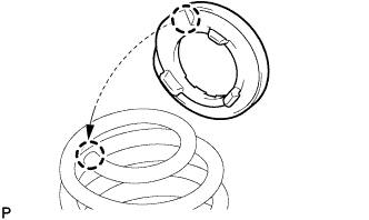
Install the coil spring insulator upper so that its gap fits onto the end of rear coil spring LH.
-
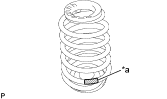
Text in Illustration *a Paint Mark Install the rear coil spring LH onto the rear axle beam.
Note
The paint mark of the coil spring should be on the underside and rear side of the vehicle.
-
-
INSTALL REAR COIL SPRING RH
Tech Tips
The installation procedure for the RH side is the same as that for the LH side.
-
TEMPORARILY TIGHTEN SHOCK ABSORBER ASSEMBLY REAR LH
-
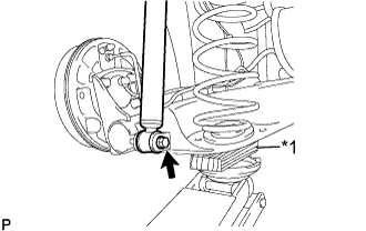
Text in Illustration *1 Wooden Block Jack up the the rear axle beam slowly, and install the shock absorber assembly rear LH (lower side) onto the rear axle beam.
-
Temporarily tighten the bolt.
-
-
TEMPORARILY TIGHTEN SHOCK ABSORBER ASSEMBLY REAR RH
Tech Tips
The installation procedure for the RH side is the same as that for the LH side.
-
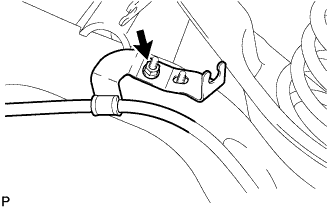
INSTALL PARKING BRAKE CABLE ASSEMBLY NO.3
-
Install the parking brake cable assembly No. 3 with the nut.
- Torque:
- 6.0 N*m { 61 kgf*cm, 53 in.*lbf }
-
-
INSTALL PARKING BRAKE CABLE ASSEMBLY NO.2
Tech Tips
The installation procedure for the RH side is the same as that for the LH side.
-
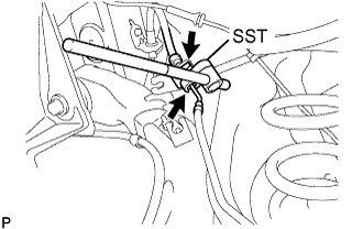
CONNECT REAR LH FLEXIBLE HOSE
-
Connect the rear LH flexible hose to the rear axle beam with a new clip.
-
Using SST, install the brake tube.
- SST
- 09023-00101
- Torque:
- 15.2 N*m { 155 kgf*cm, 11 ft.*lbf }
-
-
CONNECT REAR RH FLEXIBLE HOSE
Tech Tips
The installation procedure for the RH side is the same as that for the LH side.
-
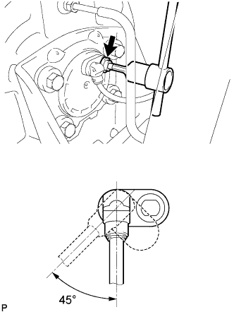
INSTALL REAR SPEED SENSOR
-
Using "TORX" socket wrench T30, install the speed sensor with the screw.
- Torque:
- 8.0 N*m { 82 kgf*cm, 71 in.*lbf }
Note
When turning the speed sensor to insert it, the turning angle should be less than 45° to avoid damaging the O-ring.
Tech Tips
If the installation portion of the sensor is dirty, clean it and reinstall the sensor.
-
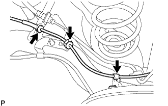
Connect the 3 clamps.
Tech Tips
The installation procedure for the RH side is the same as that for the LH side.
-
-
FULLY TIGHTEN REAR AXLE BEAM ASSEMBLY
-
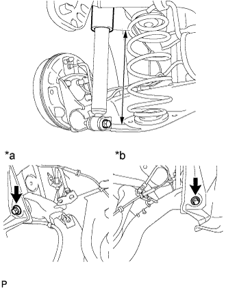
Text in Illustration *a LH Side *b RH Side Stabilize the suspension.
If it is impossible to tighten the bolt in this position, support the rear axle spring seat with a jack.
Length of shock absorber 230 mm (9.1 in.) -
Fully tighten the 2 bolts.
- Torque:
- 123 N*m { 1,255 kgf*cm, 91 ft.*lbf }
-
-
FULLY TIGHTEN SHOCK ABSORBER ASSEMBLY REAR LH
-
Fully tighten the bolt.
- Torque:
- 48 N*m { 489 kgf*cm, 35 ft.*lbf }
-
-
FULLY TIGHTEN SHOCK ABSORBER ASSEMBLY REAR RH
Tech Tips
The installation procedure for the RH side is the same as that for the LH side.
-
FILL RESERVOIR WITH BRAKE FLUID
Fluid SAE J1704 or FMVSS No. 116 DOT4 -
BLEED BRAKE MASTER CYLINDER
Tech Tips
If the master cylinder has been disassembled or if the reservoir becomes empty, bleed the air from the master cylinder.
-
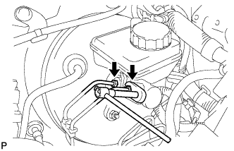
Using a 10 mm union nut wrench, separate the brake tubes from the master cylinder (w/o VSC).
-
Using a 12 mm union nut wrench, separate the brake tubes from the master cylinder (w/ VSC).
-
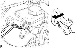
Slowly depress the brake pedal and hold it there (Step A).
-
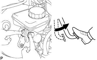
Block the outer holes with your fingers, and release the brake pedal (Step B).
-
Repeat step A and B 3 or 4 times.
-
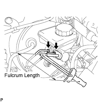
Using a 10 mm union nut wrench, install the brake tubes to the master cylinder (w/o VSC).
- Torque:
- without 10 mm union nut wrench
- 15 N*m { 155 kgf*cm, 11 ft.*lbf }
- with 10 mm union nut wrench
- 14 N*m { 143 kgf*cm, 10 ft.*lbf }
Note
-
This torque value can be obtained by using a torque wrench with a fulcrum length of 300 mm (11.8 in.) and a 10 mm union nut wrench with a fulcrum length of 22 mm (0.886 in.) Click here.
-
This torque value is effective when the union nut wrench is parallel to a torque wrench.
-
Using a 12 mm union nut wrench, install the brake tubes to the master cylinder (w/ VSC).
- Torque:
- without 12 mm union nut wrench
- 20 N*m { 204 kgf*cm, 15 ft.*lbf }
- with 12 mm union nut wrench
- 18 N*m { 184 kgf*cm, 13 ft.*lbf }
Note
-
This torque value can be obtained by using a torque wrench with a fulcrum length of 300 mm (11.8 in.) and a 12 mm union nut wrench with a fulcrum length of 30 mm (1.18 in.) Click here.
-
This torque value is effective when the union nut wrench is parallel to a torque wrench.
-
-
BLEED BRAKE LINE
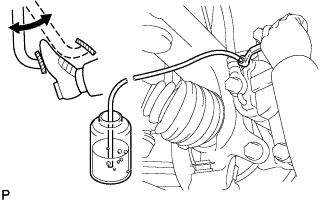
-
Connect a vinyl tube to the bleeder plug.
-
Depress the brake pedal several times, then loosen the bleeder plug with the pedal depressed (Step C).
-
At the point where the fluid stops coming out, tighten the bleeder plug, then release the brake pedal (Step D).
-
Repeat step C and D until all the air in the fluid is completely bled out.
-
Tighten the bleeder plug.
- Torque:
- 6.5 N*m { 66 kgf*cm, 58 in.*lbf }
-
Repeat the above procedure to bleed the air out of the brake line for each wheel.
-
-
CHECK FLUID LEVEL IN RESERVOIR
-
Check the fluid level and add fluid if necessary.
Fluid SAE J1704 or FMVSS No. 116 DOT4
-
-
INSTALL REAR WHEEL
- Torque:
- 103 N*m { 1,050 kgf*cm, 76 ft.*lbf }
-
CONNECT CABLE TO NEGATIVE BATTERY TERMINAL
- Torque:
- 5.4 N*m { 55 kgf*cm, 48 in.*lbf }
-
CHECK FOR BRAKE FLUID LEAKAGE
-
INSPECT REAR WHEEL ALIGNMENT
-
CHECK ABS SENSOR SIGNAL (w/o VSC)
-
CHECK VSC SENSOR SIGNAL (w/ VSC)