FRONT STABILIZER BAR INSTALLATION

-
INSTALL FRONT STABILIZER BAR
-
INSTALL FRONT NO. 1 STABILIZER BAR BUSH
-
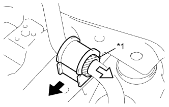
Text in Illustration *1 Bush Stopper 
Front Side 
Outer Side Install the 2 front No. 1 stabilizer bar bushes to the front stabilizer bar.
Tech Tips
-
Install the front No. 1 stabilizer bar bush to the inner side of the bush stopper on the front stabilizer bar.
-
Install the front No. 1 stabilizer bar bush to the front stabilizer bar with its cut line facing the front.
-
-
-
INSTALL FRONT NO. 1 STABILIZER BRACKET LH
-
Install the front No. 1 stabilizer bracket LH with the 2 bolts.
- Torque:
- 35 N*m { 357 kgf*cm, 26 ft.*lbf }
-
-
INSTALL FRONT NO. 1 STABILIZER BRACKET RH
-
Install the front No. 1 stabilizer bracket RH with the 2 bolts.
- Torque:
- 35 N*m { 357 kgf*cm, 26 ft.*lbf }
-
-
INSTALL STEERING GEAR ASSEMBLY
-
Install the steering gear assembly to the suspension crossmember sub-assembly with the 2 bolts and the 2 nuts.
- Torque:
- 89 N*m { 902 kgf*cm, 65 ft.*lbf }
Note
Keep the nut from rotating while turning the bolt.
-
Install the No. 1 steering column hole cover sub-assembly onto the steering gear assembly.
Note
Install the No. 1 steering column hole cover sub-assembly securely.
-
-
INSTALL FRONT SUSPENSION CROSSMEMBER SUB-ASSEMBLY
-
Using a transmission jack, support the front suspension crossmember sub-assembly.
-
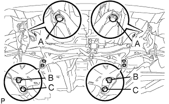
Install the front suspension crossmember sub-assembly with the 6 bolts.
- Torque:
- for bolt A
- 85 N*m { 867 kgf*cm, 63 ft.*lbf }
- for bolt B
- 128 N*m { 1305 kgf*cm, 95 ft.*lbf }
- for bolt C
- 48 N*m { 489 kgf*cm, 35 ft.*lbf }
-
Install the engine mounting control bracket with the 3 bolts.
- Torque:
- 52 N*m { 530 kgf*cm, 38 ft.*lbf }
-
Remove the engine sling device.
-
Remove the 2 bolts, No. 1 engine hanger and the No. 2 engine hanger.
-
-
INSTALL FRONT SUSPENSION LOWER ARM LH
-
Push the front suspension lower arm No. 1 downward, install the front lower ball joint and tighten the castle nut and a new clip.
- Torque:
- 98 N*m { 1,000 kgf*cm, 72 ft.*lbf }
Note
Retighten the castle nut and clip within a turning angle of 60° after aligning the hole of the clip with the castle nut.
-
-
INSTALL FRONT SUSPENSION LOWER ARM RH
Tech Tips
The installation procedure for the RH side is the same as that for the LH side.
-
INSTALL FRONT STABILIZER BOLT
-
Install the 4 retainers, 4 cushions, No. 2 retainer and the stabilizer bolt.
-
Text in Illustration *a Turn *b Hold While holding the stabilizer bolt with a wrench, install the 2 new nuts.
- Torque:
- 18 N*m { 184 kgf*cm, 13 ft.*lbf }
Tech Tips
Support the front suspension lower arm with a jack.
-
Perform the above procedure on the opposite side.
-
-
INSTALL TIE ROD END SUB-ASSEMBLY LH
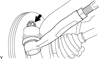
-
Connect the tie rod end to the steering knuckle and install it with the castle nut and a new cotter pin.
- Torque:
- 33 N*m { 336 kgf*cm, 24 ft.*lbf }
Note
Retighten the castle nut and cotter pin within a turning angle of 60° after aligning the hole of the cotter pin with the castle nut.
-
-
INSTALL TIE ROD END SUB-ASSEMBLY RH
Tech Tips
The installation procedure for the RH side is the same as that for the LH side.
-
INSTALL NO. 1 STEERING COLUMN HOLE COVER SUB-ASSEMBLY
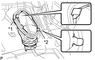
Text in Illustration *1 Clip A *2 Clip B
-
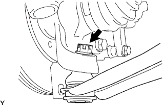
Install clip B onto the body and install the No. 1 steering column hole cover sub-assembly onto the body with clip A.
Note
Fit the lip of the No. 1 steering column hole cover sub-assembly correctly onto the dash panel.
-
-
INSTALL NO. 2 STEERING INTERMEDIATE SHAFT ASSEMBLY
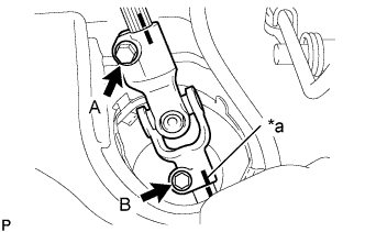
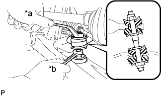
Text in Illustration *a Matchmark
-
Align the matchmarks and install the No. 2 steering intermediate shaft assembly to the steering gear assembly with bolt B.
- Torque:
- 35 N*m { 360 kgf*cm, 26 ft.*lbf }
-
Tighten bolt A.
- Torque:
- 35 N*m { 360 kgf*cm, 26 ft.*lbf }
-
Release the seat belt from the steering wheel assembly.
-
-
INSTALL STEERING COLUMN HOLE COVER PLATE
-
Engage the steering column hole cover plate.
-
-
INSTALL EXHAUST FRONT PIPE ASSEMBLY
-
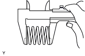
Using vernier calipers, measure the free length of the compression spring.
Minimum length 40.5 mm (1.594 in.)
-
If the length is not as specified, replace the compression spring.
-
-
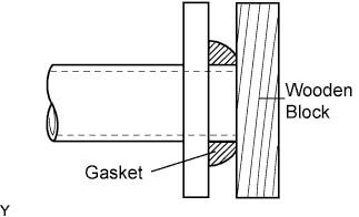
Using a plastic hammer and a wooden block, tap in a new exhaust pipe gasket until its surface is flush with the exhaust manifold.
Note
-
Be sure to install the exhaust pipe gasket in the correct direction.
-
Do not damage the outer surface of the exhaust pipe gasket.
-
Do not reuse the exhaust pipe gasket.
-
Do not push in the gasket with the exhaust pipe when connecting it.
-
-
Install the exhaust front pipe assembly and a new exhaust pipe gasket with the 2 compression springs and 2 bolts.
- Torque:
- 45 N*m { 459 kgf*cm, 33 ft.*lbf }
-
Install the exhaust pipe No.4 support.
-
Install the bolt and clamp.
- Torque:
- 32 N*m { 326 kgf*cm, 24 ft.*lbf }
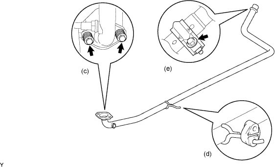
Note
-
Clamp marks and stamping should be aligned.
-
-
INSTALL FRONT WHEELS
- Torque:
- 103 N*m { 1050 kgf*cm, 76 ft.*lbf }
-
INSTALL COWL TOP PANEL OUTER
-
Install the cowl top panel outer with the 10 bolts.
- Torque:
- 9.2 N*m { 94 kgf*cm, 81 in.*lbf }
-
Engage the grommet and install the wire harness.
-
Engage the wire harness clamp.
-
-
INSTALL FRONT NO. 1 VENTILATOR SEAL
-
Install the front No. 1 ventilator seal with the 2 clips.
-
-
INSTALL FRONT AIR SHUTTER SEAL RH
-
Install the front air shutter seal RH with the 2 clips.
-
-
INSTALL FRONT WIPER MOTOR AND LINK ASSEMBLY
-
INSPECT FOR EXHAUST GAS LEAK
-
INSPECT AND ADJUST FRONT WHEEL ALIGNMENT