FRONT WHEEL ALIGNMENT INSPECTION

Note
For vehicles equipped with VSC, if wheel alignment has been adjusted, and if suspension or underbody components have been removed/installed or replaced, be sure to perform the following initialization procedure in order for the system to function normally:
-
Disconnect the negative battery terminal for more than 2 seconds.
-
Reconnect the negative battery terminal.
-
INSPECT TIRES
-
Check the tires for wear and proper inflation pressure.
Cold Tire Inflation Pressure Engine Type Tire Size Condition Front
kPa (kgf/cm2, psi)
Rear
kPa (kgf/cm2, psi)
1KR-FE 155/65R14 75T Driving below 160 km/h (100mph) 220 (2.2, 32) 220 (2.2, 32) Driving over 160 km/h (100mph) 230 (2.3, 34) 230 (2.3, 34) 2WZ-TV Driving below 160 km/h (100mph) 240 (2.4, 35) 220 (2.2, 32) Driving over 160 km/h (100mph) 240 (2.4, 35) 230 (2.3, 34) -
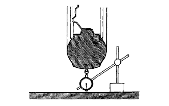
Using a dial indicator, check the tire runout.
Tire runout 1.4 mm (0.055 in.) or less
-
-
MEASURE VEHICLE HEIGHT
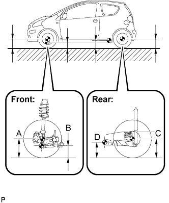
Vehicle height (unloaded vehicle) Engine Type A-B C-D 1KR-FE 88 mm (3.46 in.) 22 mm (0.87 in.) 2WZ-TV 89 mm (3.50 in.) 22 mm (0.87 in.) Measuring points A Ground clearance of front wheel center B Ground clearance of lower suspension arm front bolt center C Ground clearance of rear wheel center D Ground clearance of rear axle beam set bolt center Note
Before inspecting the wheel alignment, inspect the vehicle height.
Tech Tips
Bounce the vehicle up and down at the corners to stabilize the suspension before inspecting the vehicle height.
-
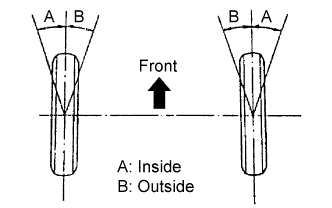
INSPECT TOE-IN
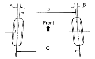
Toe-in (unloaded vehicle) A+B C-D -0°06' to 0°21'
(-0.1°to 0.35°)
-0.9 mm to 3.1 mm
(-0.04 in. to 0.12 in.)
Tech Tips
Measure C-D only when A+B can not be measured.
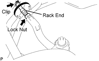
If the toe-in is not within the specified range, adjust it at the rack ends.
-
ADJUST TOE-IN
-
Remove the rack boot set clips
-
Loosen the tie rod end lock nuts.
-
Turn the right and left rack ends uniformly to adjust the toe-in.
Toe-in 0.1 mm to 2.1 mm (0 in. to 0.08 in. ) Tech Tips
Try to adjust the toe-in to the middle of the specified range.
-
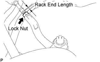
Make sure that the lengths of the right and left rack ends are the same.
Rack end length difference 1.5 mm (0.059 in.) or less -
Torque the tie rod end lock nuts.
- Torque:
- 47 N*m { 479 kgf*cm, 35 ft.*lbf }
-
Place the boots on the seats and install the clips.
Tech Tips
Make sure that the boots are not twisted.
-
-
INSPECT WHEEL TURNING ANGLE
-
Fully turn the steering wheel left and right, and measure the wheel turning angle.
Wheel turning angle (unloaded vehicle) Inside Wheel Outside Wheel
(Reference)
36°55' to 40°55'
(36.92° to 40.92°)
32°23'
(32.38°)
If the right and left inside wheel angles are not within the specified range, check the right and left rack end lengths.
-
-
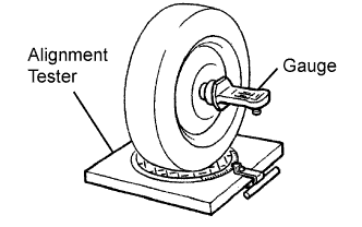
INSPECT CAMBER, CASTER AND STEERING AXIS INCLINATION
-
Install the camber-caster-steering axis inclination gauge at the center of the axle hub or drive shaft and position the front wheel on the alignment tester.
-
Inspect the camber, caster and steering axis inclination.
Camber, caster and steering axis inclination (unloaded vehicle) Engine Type Camber Caster Steering Axis Inclination
(Reference)
1KR-FE -1°32' to -0°02'
(-1.53° to -0.03°)
2°02' to 3°32'
(2.03° to 3.53° )
9°33'
(9.55°)
2WZ-TV -1°32' to -0°02'
(-1.53° to -0.03°)
1°58' to 3°28'
(1.97° to 3.47° )
9°33'
(9.55°)
Note
The tolerance for the difference between the left and right wheels is 30' (0.5°) or less for both the camber and caster.
Tech Tips
There is no camber, caster or steering axis inclination adjusting mechanism.
If the measured values are not within the specified ranges, inspect the suspension parts and replace them if necessary.
-
-
FRONT WHEELS FACING STRAIGHT AHEAD
-
DISCONNECT CABLE FROM NEGATIVE BATTERY TERMINAL (w/ VSC)
Note
Disconnect the negative battery terminal for more than 2 seconds.
-
CONNECT CABLE TO NEGATIVE BATTERY TERMINAL (w/ VSC)