ANTI-LOCK BRAKE SYSTEM TERMINALS OF ECU

-
Terminals of ECU
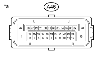
Text in Illustration *a Component without harness connected
(Skid Control ECU (Brake Actuator Assembly))
Terminals No. (Symbol) Terminal Description 1 (+BM) Motor relay power supply 2 (SP1) Speed signal output for meter 3 (WA) ABS warning light output 4 (FR-) Front RH wheel speed signal input 6 (D/G) Diagnosis tester communication line 8 (FL-) Front LH wheel speed signal input 13 (GND2) Actuator pump motor ground 15 (TS) Sensor diagnosis check input 16 (FR+) Front RH wheel speed sensor power supply 17 (RR+) Rear RH wheel speed sensor power supply 18 (RL-) Rear LH wheel speed signal input 19 (FL+) Front LH wheel speed sensor power supply 20 (TC) Diagnosis code check input 25 (+BS) Solenoid valves power supply 27 (EBDW) Brake warning line 28 (IG1) ECU power supply 29 (RR-) Rear RH wheel speed signal input 30 (STP) Stop light switch input 31 (RL+) Rear LH wheel speed sensor power supply 33 (PKB) Parking brake switch input 38 (GND1) Skid control ECU ground -
Terminal inspection
-
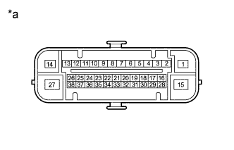
Text in Illustration *a Front view of wire harness connector
(to Skid Control ECU (Brake Actuator Assembly))
Disconnect the skid control ECU connector and measure the resistance and voltage on the wire harness side.
Tech Tips
Voltage cannot be measured with the connector connected to the skid control ECU as the connector is water resistant.
Terminal No. (Symbol) Wiring Color Terminal Description Conditions Specified Conditions A46-1 (+BM) - Body ground B - Body ground Motor relay power supply Always 11 to 14 V A46-3 (WA) - Body ground P - Body ground ABS warning light output Ignition switch ON
ABS warning light on
5 to 14 V A46-13 (GND2) - Body ground W-B - Body ground Actuator pump motor ground Always Below 1 Ω A46-25 (+BS) - Body ground R - Body ground Solenoid valves power supply Always 11 to 14 V A46-27 (EBDW) - Body ground W - Body ground Brake warning line Ignition switch ON
Brake warning light on
5 to 14 V A46-28 (IG1) - Body ground L - Body ground ECU power supply Ignition switch ON 11 to 14 V A46-30 (STP) - Body ground G - Body ground Stop light switch input Stop light switch ON → OFF (Brake pedal depressed → released) 11 to 14 V* → Below 1.5 V A46-33 (PKB) - Body ground Y - Body ground Parking brake switch input Parking brake switch on → Parking brake switch off Below 1 Ω → 10 kΩ or higher A46-38 (GND1) - Body ground BR - Body ground Skid control ECU ground Always Below 1 Ω Tech Tips
*: The standard voltage value varies depending on the +BS terminal voltage value. The standard voltage is 85% of the +BS terminal voltage.
-