ANTI-LOCK BRAKE SYSTEM TERMINALS OF ECU

-
Terminals of ECU
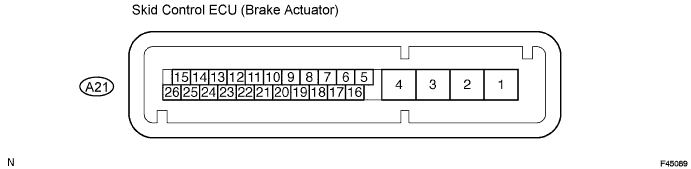
Symbols (Terminals No.) Terminal Description GND2 (A21-1) Actuator pump motor ground +BM (A21-2) Motor relay power supply +BS (A21-3) Solenoid valves power supply GND1 (A21-4) Skid control ECU ground FL- (A21-5) Front LH wheel speed signal input RL+ (A21-6) Rear LH wheel speed sensor power supply RR+ (A21-8) Rear RH wheel speed sensor power supply FR+ (A21-9) Front RH wheel speed sensor power supply FR- (A21-10) Front RH wheel speed signal input D/G (A21-11) Diagnosis tester communication line EBDW (A21-12) Brake warning line TS (A21-13) Sensor diagnosis check input PKB (A21-14) Parking brake switch input FL+ (A21-16) Front LH wheel speed sensor power supply RL- (A21-17) Rear LH wheel speed signal input IG1 (A21-18) ECU power supply RR- (A21-19) Rear RH wheel speed signal input STP (A21-20) Stop light switch input WA (A21-22) ABS warning light output SP1 (A21-23) Speed signal output for meter TC (A21-25) Diagnosis code check input -
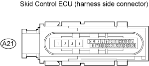
Terminal inspection
-
Disconnect the connector and measure the resistance and voltage on the wire harness side.
Tech Tips
Voltage cannot be measured with the connector connected to the skid control ECU as the connector is water resistant.
Symbols Wiring Color Terminal Description Conditions Specified Conditions GND2 (A21-1) - Body ground W-B - Body ground Actuator pump motor ground Always Below 1 Ω +BM (A21-2) - Body ground B - Body ground Motor relay power supply Always 10 to 14 V +BS (A21-3) - Body ground R - Body ground Solenoid valves power supply Always 10 to 14 V GND1 (A21-4) - Body ground BR - Body ground Skid control ECU ground Always Below 1 Ω EBDW (A21-12) - Body ground W - Body ground Brake warning line Ignition switch ON (IG)
Brake warning light ON
5 to 14 V PKB (A21-14) - Body ground Y - Body ground Parking brake switch input Parking brake switch ON Below 1 Ω IG1 (A21-18) - Body ground L - Body ground ECU power supply Ignition switch ON (IG) 10 to 14 V STP (A21-20) - Body ground G - Body ground Stop light switch input Stop light switch ON
Brake pedal depressed
8 to 14 V STP (A21-20) - Body ground G - Body ground Stop light switch input Stop light switch ON
Brake pedal released
Below 3 V WA (A21-22) - Body ground P - Body ground ABS warning light output Ignition switch ON (IG)
ABS warning light ON
5 to 14 V
-