FRONT DRIVE SHAFT REASSEMBLY

-
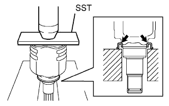
INSTALL FRONT DRIVE SHAFT DUST COVER
-
Using SST and a press, install a new dust cover, as shown in the illustration.
- SST
- 09527-10011
Note
-
Install the dust cover securely.
-
Do not damage the dust cover.
-
-
INSTALL FRONT DRIVE SHAFT HOLE SNAP RING
-
Install a new snap ring onto the inboard joint assembly.
-
-
INSTALL FRONT AXLE OUTBOARD JOINT BOOT
-
Wrap the spline of the outboard joint assembly with vinyl tape to prevent it from being damaged.
-
Install new parts onto the outboard joint assembly in the following order.
-
Outboard joint boot No. 2 clamp
-
Outboard joint boot
-
Outboard joint boot clamp
-
-
Pack the outboard joint assembly with grease.
Standard Engine Grease Capacity 1KR-FE 72 to 82 g (2.54 to 2.89 oz.) 2WZ-TV 78 to 88 g (2.75 to 3.10 oz.) -
Install the outboard joint boot onto the outboard joint assembly.
-
-
INSTALL FRONT AXLE OUTBOARD JOINT BOOT NO. 2 CLAMP
-
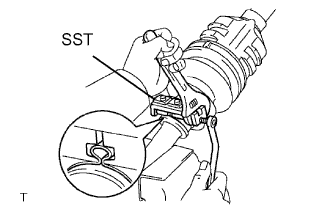
Secure the outboard joint boot No. 2 clamp onto the boot.
-
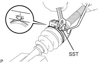
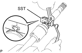
Place SST onto the outboard joint boot No. 2 clamp.
- SST
- 09521-24010
-
Tighten SST so that the outboard joint boot No. 2 clamp is pinched.
Note
Do not overtighten SST.
-
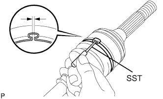
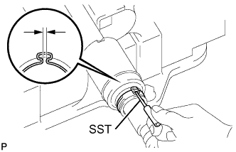
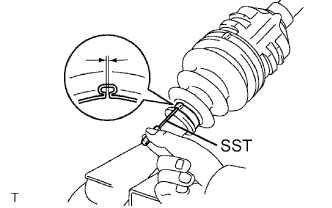
Using SST, adjust the clearance of the outboard joint boot No. 2 clamp.
- SST
- 09240-00020
Standard Clearance 0.8 mm (0.031 in.) or less
-
-
INSTALL FRONT AXLE OUTBOARD JOINT BOOT CLAMP
-
Secure the outboard joint boot clamp onto the boot.
-
Place SST onto the outboard joint boot clamp.
- SST
- 09521-24010
-
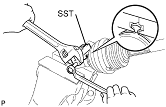
Tighten SST so that the outboard joint boot clamp is pinched.
Note
Do not overtighten SST.
-
Using SST, adjust the clearance of the outboard joint boot clamp.
- SST
- 09240-00020
Standard Clearance 0.8 mm (0.031 in.) or less
-
-
INSTALL FRONT DRIVE SHAFT DAMPER (for 2WZ-TV RH Side)
-
Install the drive shaft damper onto the outboard joint assembly.
Note
Install the damper in the correct direction.
-
Set the distance, as described below.
Standard Distance (A) 508 to 512 mm (20.00 to 20.15 in.)
-
-
INSTALL DRIVE SHAT DAMPER SETTING CLAMP (for 2WZ-TV RH Side)
-
Secure the drive shaft damper setting clamp onto the drive shaft damper.
-
Place SST onto the drive shaft damper clamp.
- SST
- 09521-24010
-
Tighten the SST so that the drive shaft setting clamp is pinched.
Note
Do not overtighten the SST.
-
Using SST, adjust the clearance of the drive shaft setting clamp.
- SST
- 09240-00020
Standard Clearance 0.8 mm (0.031 in.) or less
-
-
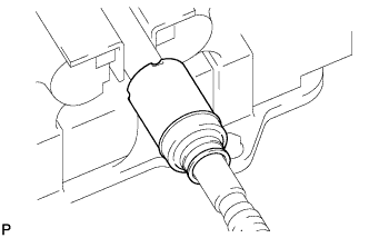
INSTALL FRONT DRIVE INBOARD JOINT ASSEMBLY
-
Wrap the spline of the outboard joint assembly with vinyl tape to prevent it from being damaged.
-
Install new parts onto the outboard joint assembly in the following order.
-
Inboard joint boot clamp
-
Inboard joint boot
-
Inboard joint boot No. 2 clamp
-
-
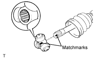
Align the matchmarks and install the tripod joint assembly onto the outboard joint assembly.
-
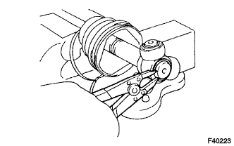
Using a brass bar and hammer, install the tripod joint assembly.
Note
Do not tap the roller.
-
Using a snap ring expander, install a new front drive inner shaft snap ring.
-
Pack the inboard joint assembly with grease.
Grease capacity 98 to 112 g (3.46 to 3.95 oz.) -
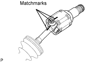
Align the matchmarks and install the inboard joint assembly onto the outboard joint assembly.
-
-
INSTALL FRONT AXLE INBOARD JOINT BOOT
-
Install the inboard joint boot onto the inboard joint assembly.
-
-
INSTALL FRONT AXLE INBOARD JOINT BOOT CLAMP
-
Secure the inboard joint boot clamp onto the boot.
-
Place SST onto the inboard joint boot clamp.
- SST
- 09521-24010
-
Tighten SST so that the inboard joint boot clamp is pinched.
Note
Do not overtighten SST.
-
Using SST, adjust the clearance of the inboard joint boot clamp.
- SST
- 09240-00020
Standard Clearance 0.8 mm (0.031 in.) or less
-
-
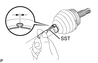
INSTALL FRONT AXLE INBOARD JOINT BOOT NO. 2 CLAMP
-
Secure the inboard joint boot clamp No. 2 onto the boot.
-
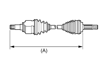
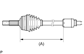
Adjust dimension (A) until the drive shaft is within the specified length.
Dimension (A) Engine LH (mm) RH (mm) 1KR-FE 580.3 770.3 2WZ-TV 523.8 828.3 -
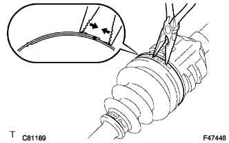
Using needle-nose pliers, align the concave part with the protrusion of the inboard joint boot clamp No. 2 in order to fix it.
Note
-
Do not scratch the inboard joint boot.
-
Do not deform the claw of the hook.
-
-
-
INSPECT FRONT DRIVE SHAFT ASSEMBLY
-
Check whether the front drive shaft assembly is within the following dimensions.
Dimension (A) Engine LH (mm) RH (mm) 1KR-FE 580.3 770.3 2WZ-TV 523.8 828.3 -
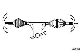
Check for noticeable looseness when turning the joint up and down, left and right, and in the thrust direction.
-
Check for cracks, damage and grease leakage on the joint boot.
Note
Keep the front drive shaft assembly level while moving it.
-