SHIFT LEVER ON-VEHICLE INSPECTION

-
INSPECT SHIFT LOCK SOLENOID
-
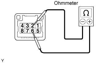
Disconnect the indicator light wire connector.
-
Using an ohmmeter, measure the resistance between terminals 2 and 6.
Standard Resistance 30 to 35 Ω at 20°C (68°F) If the resistance is not as specified, replace the shift lever assembly.
-
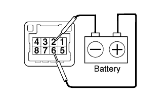
Check the solenoid operating sound when applying battery voltage across terminals 2 and 6.
If the solenoid does not operate, replace the shift lever assembly.
-
Connect the indicator light wire connector.
-
-
INSPECT TRANSMISSION SHIFT MAIN SWITCH
-
Disconnect the indicator light wire connector.
-
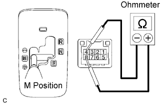
Move the shift lever to the M position.
-
Using an ohmmeter, measure the resistance according to the value in the table below.
Standard Resistance Shift position Terminals Specified condition M 4 - 8 Below 1 Ω -
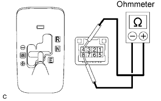
Move the shift lever to the E position.
-
Using an ohmmeter, measure the resistance according to the value in the table below.
Standard Resistance Shift position Terminals Specified condition E 4 - 8 10 kΩ or higher If the result is not as specified, replace the shift lever assembly.
-
Connect the indicator light wire connector.
-
-
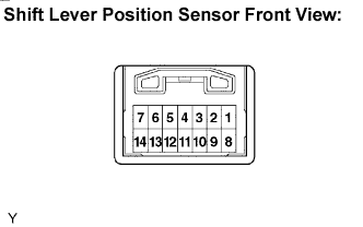
INSPECT SHIFT LEVER POSITION SENSOR
-
Disconnect the shift lever position sensor connector.
-
Using an ohmmeter, measure the resistance according to the values in the table below.
Standard Resistance Shift position Terminals Specified condition R 4 - 9 - 10 - 13 Below 1 Ω N 4 - 2 - 10 - 6 Below 1 Ω E, M 4 - 2 - 3 - 13 Below 1 Ω + 11 - 5 Below 1 Ω M 11 - 5 - 12 10 kΩ or higher - 11 - 12 Below 1 Ω If the result is not as specified, replace the shift lever assembly.
-
Connect the shift lever position sensor connector.
-