MULTI-MODE MANUAL TRANSAXLE ECU REMOVAL

-
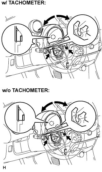
REMOVE STEERING COLUMN UPPER COVER
-
Remove the 2 screws while turning the steering wheel to the right and left.
-
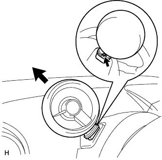
Disengage the 4 claws and remove the steering column cover upper.
-
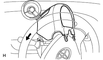
Remove the steering column cover upper, as shown in the illustration (w/ tachometer).
-
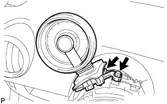
If the steering column cover upper is difficult to remove, loosen the screw behind the tachometer, pull up and extend the tachometer, and then remove the steering cover upper (w/ tachometer).
-
-
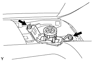
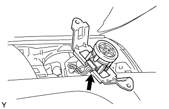
REMOVE TACHOMETER ASSEMBLY (w/ Tachometer)
-
Disconnect the connector.
-
Remove the bolt and tachometer.
-
-
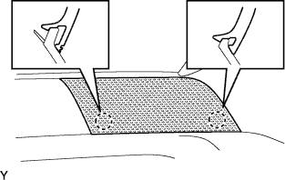
SEPARATE FRONT DOOR OPENING TRIM WEATHERSTRIP LH
-
Separate the front door opening trim weatherstrip LH.
-
-
SEPARATE FRONT DOOR OPENING TRIM WEATHERSTRIP RH
Tech Tips
Use the same procedure as for the LH side.
-
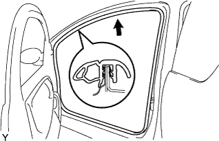
REMOVE FRONT PILLAR GARNISH LH (w/ Curtain Shield Airbag)
Tech Tips
Use the same procedure as for the RH side.
-
REMOVE FRONT PILLAR GARNISH RH (w/ Curtain Shield Airbag)
Tech Tips
Use the same procedure as for the LH side.
-
REMOVE FRONT PILLAR GARNISH LH (w/o Curtain Shield Airbag)
Tech Tips
Use the same procedure as for the RH side.
-
REMOVE FRONT PILLAR GARNISH RH (w/o Curtain Shield Airbag)
Tech Tips
Use the same procedure as for the LH side.
-
REMOVE INSTRUMENT PANEL SPEAKER PANEL SUB-ASSEMBLY NO. 2
-
Disengage the 2 claws.
-
-
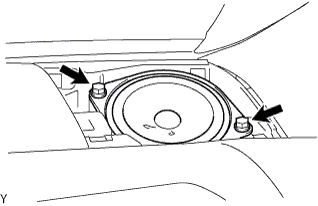
REMOVE FRONT NO. 1 SPEAKER ASSEMBLY (w/o Power Window)
-
Remove the 2 screws.
-
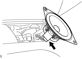
Disconnect the connector.
-
-
REMOVE FRONT NO. 1 SPEAKER ASSEMBLY (w/ Power Window)
-
Remove the 2 screws.
-
Disconnect the connector and remove the front No. 1 speaker.
-
-
REMOVE INSTRUMENT PANEL SPEAKER PANEL SUB-ASSEMBLY NO.1
Tech Tips
Use the same procedure as for the No. 2 side.
-
REMOVE FRONT NO. 1 SPEAKER ASSEMBLY (w/o Power Window)
Tech Tips
Use the same procedure as for the RH side.
-
REMOVE FRONT NO. 1 SPEAKER ASSEMBLY (w/ Power Window)
Tech Tips
Use the same procedure as for the RH side.
-
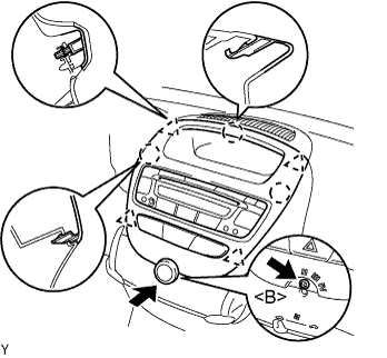
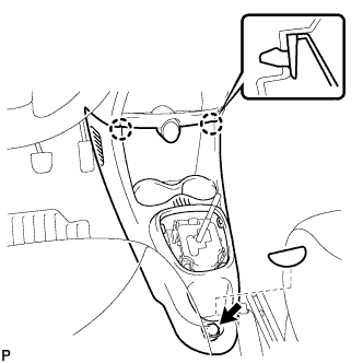
REMOVE INSTRUMENT CLUSTER FINISH PANEL SUB-ASSEMBLY CENTER
-
Remove the control knob.
-
Remove the screw <B>.
-
Disengage the 4 clips and 3 claws and remove the cluster finish panel by pulling it up from underneath.
-
Disconnect the connectors and remove the instrument cluster finish panel center.
-
-
REMOVE INSTRUMENT PANEL ASSEMBLY
-
Disengage the 2 claws and open the cover.
-
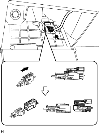
Disconnect the airbag connector, as shown in the illustration.
-
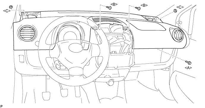
Remove the bolt <A>, 2 nuts <C> and 2 screws <B>.
-
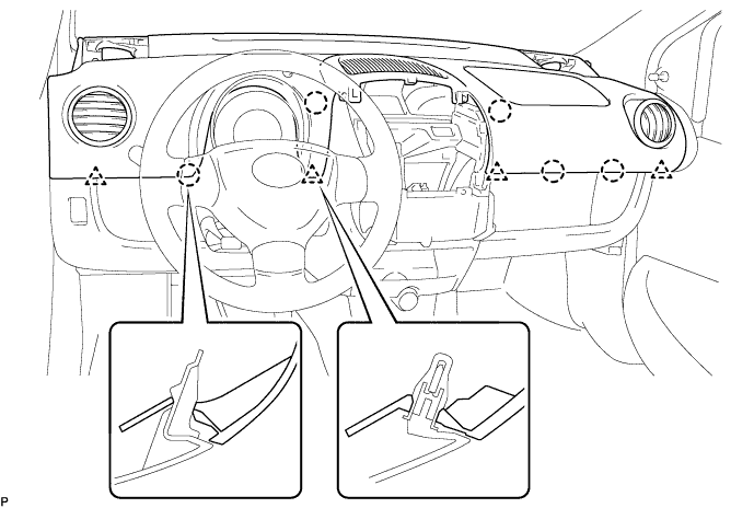
Disengage the 4 clips and 5 claws and remove the instrument panel assembly.
-
-
REMOVE COWL SIDE TRIM BOARD LH
-
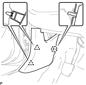
Disengage the 2 clips and claw, and remove the cowl side trim board LH.
-
-
REMOVE COWL SIDE TRIM BOARD RH
Tech Tips
Use the same procedure as for the LH side.
-
REMOVE HEATER CONTROL ASSEMBLY (for LHD)
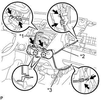
Text in Illustration *1 Defroster Cable *2 Air Inlet Cable *3 Air Mix Cable Note
Do not bend the cable when removing the heater control assembly.
-
Separate the black air mix cable from the clamp and remove the cable ring from the temperature control link.
-
Separate the white air inlet cable from the clamp and remove the cable ring from the air inlet control link.
-
Separate the blue defroster cable from the clamp and remove it from the mode link.
-
Remove the 2 screws, disengage the 2 claws and remove the heater control assembly.
-
-
REMOVE HEATER CONTROL ASSEMBLY (for RHD)
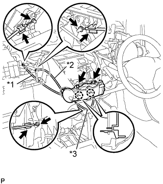
Text in Illustration *1 Air Inlet Cable *2 Defroster Cable *3 Air Mix Damper Cable Note
Do not bend the cable when removing the heater control assembly.
-
Separate the black air mix cable from the clamp and remove the cable ring from the temperature control link.
-
Separate the white air inlet cable from the clamp and remove the cable ring from the air inlet control link.
-
Separate the blue defroster cable from the clamp and remove it from the mode link.
-
Remove the 2 screws, disengage the 2 claws and remove the heater control assembly.
-
-
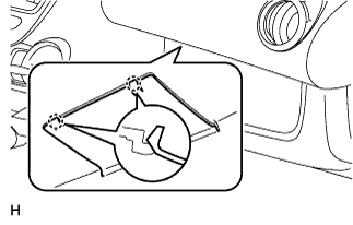
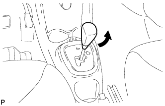
REMOVE FLOOR SHIFT POSITION INDICATOR HOUSING SUB-ASSEMBLY
-
Turn the shift knob in the direction indication by the arrow in the illustration to remove it.
-
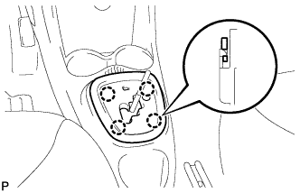
Disengage the 4 claws and remove the floor shift position indicator housing sub-assembly
-
-
REMOVE CONSOLE BOX
-
Remove the box bottom mat.
-
Remove the bolt <B>.
-
Disengage the 2 claws and remove the console box.
-
-
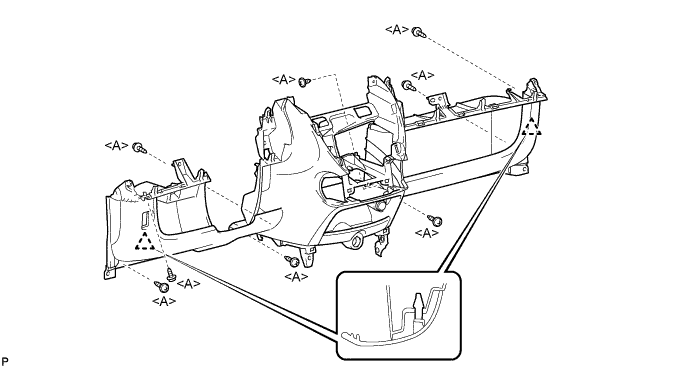
REMOVE INSTRUMENT PANEL SUB-ASSEMBLY LOWER
-
Remove the 8 screws <A>.
-
Disengage the 2 claws.
-
-
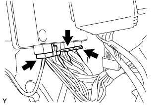
REMOVE TRANSMISSION CONTROL ECU ASSEMBLY
-
Disconnect the 3 connectors.
-
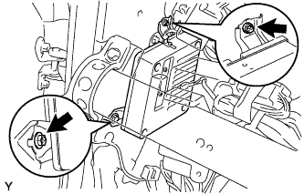
Remove the 2 screws, then remove the transmission control ECU.
-