SHIFT STROKE SENSOR INSTALLATION

-
INSTALL SHIFT STROKE SENSOR
-
Apply MP grease to a new O-ring.
-
Install the new O-ring to the shift stroke sensor.
-
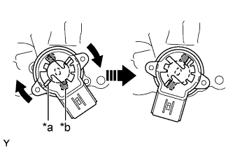
Text in Illustration *a Sensor Arm (Actuator Side) *b Sensor Arm (Sensor Side) Set the shift stroke senor so that the sensor side and the actuator side sensor arms are in the positions shown in the illustration.
-
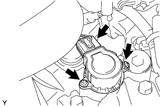
Turn the shift stroke sensor clockwise and fix it with the 2 screws.
- Torque:
- 2.0 N*m { 20 kgf*cm, 18 in.*lbf }
-
Connect the shift stroke sensor connector.
-
-
INSTALL BATTERY CLAMP SUB-ASSEMBLY
-
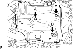
Install the battery clamp sub-assembly with the 3 bolts.
- Torque:
- Bolt A
- 7.4 N*m { 75 kgf*cm, 65 in.*lbf }
- Bolt B
- 17 N*m { 175 kgf*cm, 13 ft.*lbf }
-
-
INSTALL ENGINE ROOM RELAY BLOCK
-
Engage the 3 wire harness clamps.
-
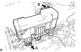
Engage the claw and install the engine room relay block.
-
Install the 2 bolts.
- Torque:
- Bolt A
- 5.4 N*m { 55 kgf*cm, 48 in.*lbf }
- Bolt B
- 8.4 N*m { 85 kgf*cm, 74 in.*lbf }
-
-
INSTALL BATTERY
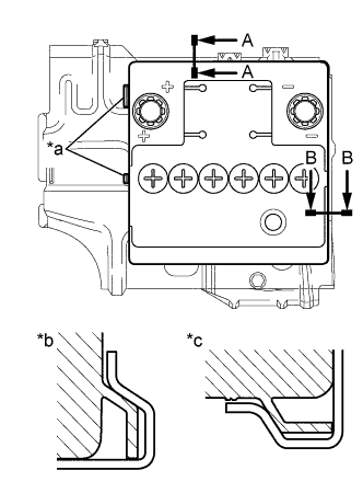
Text in Illustration *a Identification line *b A-A *c B-B
-
Install the battery onto the battery clamp sub-assembly, as shown in the illustration.
Note
-
The identification line should be seen after installing the battery.
-
The battery clamp should be in contact with the battery after the installation.
-
-
Install the battery clamp with the bolt.
- Torque:
- 15 N*m { 154 kgf*cm, 11 ft.*lbf }
-
Connect the battery positive (+) terminal with the nut.
- Torque:
- 5.4 N*m { 55 kgf*cm, 48 in.*lbf }
-
-
CONNECT CABLE TO NEGATIVE BATTERY TERMINAL
- Torque:
- 5.4 N*m { 55 kgf*cm, 48 in.*lbf }
-
INITIALIZATION OF MULTI-MODE MANUAL TRANSAXLE ECU
-
LEARNING OF MULTI-MODE MANUAL TRANSAXLE SYSTEM
-
SYNCHRONIZATION POSITION CALIBRATION