FRONT AXLE HUB INSTALLATION

-
INSTALL STEERING KNUCKLE
-
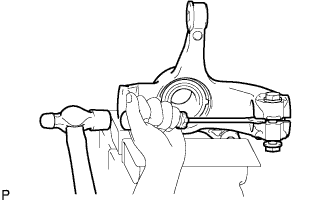
Fix the steering knuckle in a vise and provisionally install the bolt and nut. Then, using a screwdriver and hammer, widen the knuckle slit.
Note
-
Do not widen the steering knuckle slit by more than 10 mm.
-
Do not damage the steering knuckle slit portion.
-
-
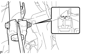
Insert the convex portion of the shock absorber into the steering knuckle slit. In addition, make the bracket edge come into contact with the steering knuckle tip.
Note
Set the nut on the front side of the vehicle.
-

Release the screwdriver. Then tighten the nut to tighten the shock absorber steering knuckle.
- Torque:
- 52 N*m { 530 kgf*cm, 38 ft.*lbf }
-
Remove any materials such as iron powder that adhere to the magnetic seal portion.
-
-
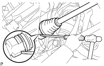
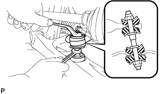
INSTALL FRONT DRIVE SHAFT ASSEMBLY
-
Coat the spline of the inboard joint shaft assembly with transaxle oil.
-
Align the shaft splines and install the drive shaft assembly with a screwdriver and hammer.
Note
-
Face the snap ring cut area downward.
-
Do not damage the oil seal.
-
Do not damage the front drive shaft assembly boot.
Tech Tips
Whether the front drive shaft assembly is securely driven in or not can be confirmed from the brass bar reaction force or sound.
-
-
-
INSTALL FRONT AXLE ASSEMBLY
-
Push the front axle assembly out of the vehicle to align the spline of the front drive shaft assembly with the front axle assembly and insert the front axle assembly.
Note
-
Do not push the front axle assembly further out of the vehicle than is necessary.
-
Do not damage the oil seal.
-
Do not damage the front drive shaft assembly boot.
-
Do not damage the speed sensor rotor.
-
Check for any foreign matter on the speed sensor rotor and insertion part.
-
-
-
INSTALL FRONT SUSPENSION ARM SUB-ASSEMBLY LOWER NO.1
-
Push the front suspension lower arm No. 1 downward, install the front lower ball joint and tighten the castle nut and a new clip.
- Torque:
- 98 N*m { 1,000 kgf*cm, 72 ft.*lbf }
Note
Retighten the castle nut and clip within a turning angle of 60° after aligning the hole of the clip with the castle nut.
-
-
INSTALL FRONT STABILIZER BAR
-
Install the stabilizer bar front with the 2 cushion retainers, 2 cushions and a nut, as shown in the illustration.
Note
Be sure to install the cushion and retainer in the correct direction.
-
Tighten the nut with a spanner (10 mm).
- Torque:
- 18 N*m { 184 kgf*cm, 13 ft.*lbf }
-
-
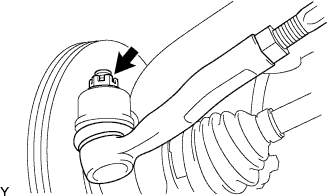
INSTALL TIE ROD END SUB-ASSEMBLY
-
Connect the tie rod end to the steering knuckle and install it with the castle nut and a new cotter pin.
- Torque:
- 33 N*m { 336 kgf*cm, 24 ft.*lbf }
Note
Retighten the castle nut and cotter pin within a turning angle of 60° after aligning the hole of the cotter pin with the castle nut.
-
-
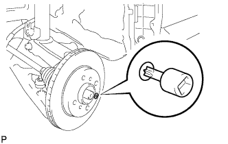
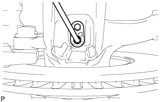
INSTALL FRONT DISC BRAKE
-
Using torx socket wrench T30, install the torx screw and front disc.
- Torque:
- 5.0 N*m { 51 kgf*cm, 44 in.*lbf }
-
-
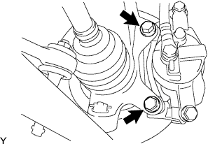
INSTALL FRONT DISC BRAKE CALIPER ASSEMBLY
-
Install the front disc brake caliper assembly onto the steering knuckle with the 2 bolts.
- Torque:
- 88 N*m { 900 kgf*cm, 65 ft.*lbf }
-
Install the flexible hose onto the shock absorber assembly with the bolt.
- Torque:
- 29 N*m { 300 kgf*cm, 22 ft.*lbf }
-
-
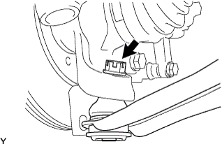
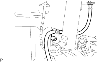
INSTALL FRONT SPEED SENSOR
-
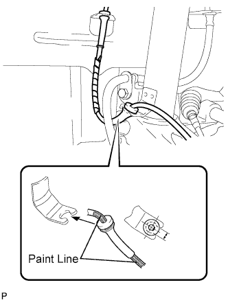
Connect the speed sensor wire to the shock absorber assembly.
Note
Insert a rubber grommet into the bracket with the painted line placed between the bracket cutouts.
-
Install the bolt and speed sensor front onto the steering knuckle.
- Torque:
- 8.0 N*m { 82 kgf*cm, 71 in.*lbf }
Note
-
Do not damage the speed sensor.
-
Keep the speed sensor free of any foreign material.
-
Do not twist the sensor wire when installing the speed sensor.
-
-
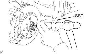
INSTALL FRONT AXLE HUB NUT
-
Install a new front axle hub nut.
- Torque:
- 216 N*m { 2,202 kgf*cm, 160 ft.*lbf }
-
Using a hammer and chisel, stake the front axle hub nut.
-
-
INSTALL FRONT WHEEL
- Torque:
- 103 N*m { 1,050 kgf*cm, 76 ft.*lbf }
-
CONNECT CABLE TO NEGATIVE BATTERY TERMINAL
- Torque:
- 5.4 N*m { 55 kgf*cm, 48 in.*lbf }
-
ADJUST FRONT WHEEL ALIGNMENT
-
CHECK ABS WARNING LIGHT