DIFFERENTIAL OIL SEAL REMOVAL

-
REMOVE FRONT WHEELS
-
DRAIN TRANSAXLE OIL
-
Remove the filler plug and gasket.
-
Remove the drain plug and gasket, and drain the oil.
-
Install the drain plug with a new gasket.
- Torque:
- 39 N*m { 400 kgf*cm, 29 ft.*lbf }
-
-
REMOVE FRONT AXLE SHAFT LH NUT
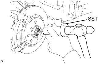
-
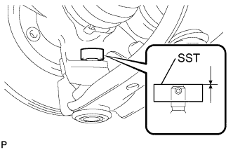
Using SST and a hammer, release the staked part of the front axle hub nut.
- SST
- 09930-00010
Note
Release the staked part of the lock nut completely. Otherwise, the screw of the drive shaft may be damaged.
-
While applying the brake, remove the front axle hub nut.
-
-
REMOVE FRONT AXLE SHAFT RH NUT
Tech Tips
The removal procedure for the RH side is the same as that for the LH side.
-
SEPARATE TIE ROD END SUB-ASSEMBLY LH
-
Remove the cotter pin and castle nut.
-
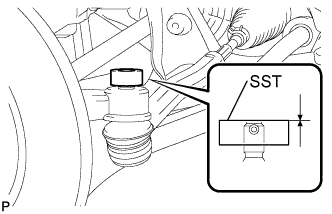
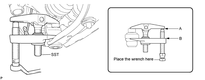
Install SST (spacer B) to the threaded section of the tie rod end.
- SST
- 09960-20010 ( 09961-02060 )
Tech Tips
Make sure the upper ends of the threaded section of the tie rod end and SST (spacer B) are aligned.
-
Using SST, separate the tie rod end from the front axle assembly.
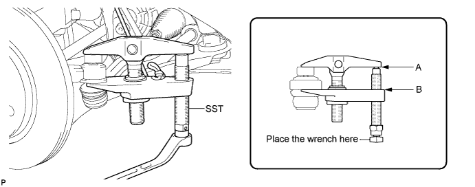
- SST
- 09960-20010 ( 09961-02010 )
Note
-
Make sure to tie the string of SST to the vehicle to prevent SST from dropping.
-
Install SST so that A and B are parallel.
-
Be sure to place the wrench on the part indicated in the illustration.
-
Do not damage the ball joint dust cover.
-
Do not damage the front disc brake dust cover.
-
-
SEPARATE TIE ROD END SUB-ASSEMBLY RH
Tech Tips
The separation procedure for the RH side is the same as that for the LH side.
-
REMOVE STABILIZER BAR FRONT
-
Hold the bolt with a spanner (10 mm) and remove the nut.
-
Remove the 2 cushion retainers and 2 cushions, and separate the front stabilizer bar.
-
-
SEPARATE FRONT SUSPENSION ARM SUB-ASSEMBLY LOWER NO.1 LH
-
Remove the clip and castle nut.
-
Install SST (spacer B) to the threaded section of the lower ball joint.
- SST
- 09960-20010 ( 09961-02060 )
Tech Tips
Make sure the upper ends of the threaded section of the lower ball joint and SST (spacer B) are aligned.
-
Using SST, separate the lower arm.
- SST
- 09960-20010 ( 09961-02010 )
Note
-
Make sure to tie the string of SST to the vehicle to prevent SST from dropping.
-
Install SST so that A and B are parallel.
-
Be sure to place the wrench on the part indicated in the illustration.
-
Do not damage the lower ball joint dust cover.
-
Do not damage the drive shaft outboard joint boots.
-
Do not damage the front disc brake dust cover.
-
-
SEPARATE FRONT SUSPENSION ARM SUB-ASSEMBLY LOWER NO.1 RH
Tech Tips
The separation procedure for the RH side is the same as that for the LH side.
-
REMOVE FRONT AXLE ASSEMBLY LH
-
Using a plastic hammer, tap the end of the front drive shaft assembly and disengage the fitting between the front drive shaft assembly and front axle assembly.
Tech Tips
If it is difficult to disengage the fitting, tap the end of the front drive shaft assembly with a brass bar and hammer.
-
Push the front axle assembly out of the vehicle to remove the front drive shaft assembly from the front axle assembly.
Note
-
Do not push the front axle assembly further out of the vehicle than is necessary.
-
Do not damage the front axle outboard joint boot.
-
Do not damage the speed sensor rotor.
-
Hang the front drive shaft assembly down with a piece of string or equivalent.
-
When removing the drive shaft, do not hit the sensor with it.
-
-
-
REMOVE FRONT AXLE ASSEMBLY RH
Tech Tips
The removal procedure for the RH side is the same as that for the LH side.
-
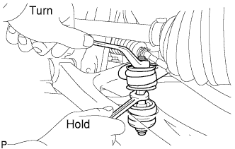
REMOVE FRONT DRIVE SHAFT ASSEMBLY LH
-
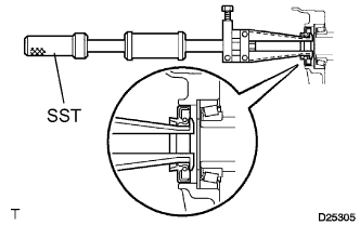
Using a screwdriver and hammer, remove the front drive shaft assembly.
Note
-
Do not damage the oil seal or the boot.
-
Do not drop the drive shaft assembly.
-
-
-
REMOVE FRONT DRIVE SHAFT ASSEMBLY RH
Tech Tips
The removal procedure for the RH side is the same as that for the LH side.
-
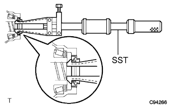
REMOVE TRANSAXLE CASE OIL SEAL
-
Using SST, remove the oil seal.
- SST
- 09308-00010
-
-
REMOVE TRANSMISSION CASE OIL SEAL
-
Using SST, remove the oil seal.
- SST
- 09308-00010
-