MULTI-MODE MANUAL TRANSAXLE SYSTEM TC and CG Terminal Circuit
DESCRIPTION
Terminals TC and CG are located in the DLC3. When performing [Initialization and Learning] without using an intelligent tester, connecting terminals TC and CG is necessary. If the TC terminal circuit is open, these calibration procedures cannot be performed without using an intelligent tester.
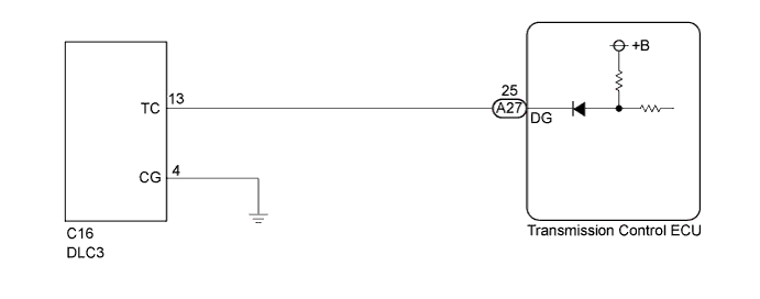
WIRING DIAGRAM
INSPECTION PROCEDURE
PROCEDURE
-
CHECK HARNESS AND CONNECTOR (TRANSMISSION CONTROL ECU - DLC3)
-
Disconnect the A27 transmission control ECU connector.
-
Measure the resistance according to the value(s) in the table below.
Standard Resistance Tester Connection Condition Specified Condition A27-25 (DG) - C16-13 (TC) Always Below 1 Ω
NG 
REPAIR OR REPLACE HARNESS OR CONNECTOR
OK 
-
-
CHECK HARNESS AND CONNECTOR (TC OF DLC3 - BODY GROUND)
-
Measure the resistance according to the value(s) in the table below.
Standard Resistance Tester Connection Condition Specified Condition C16-13 (TC) - Body ground Always 10 kΩ or higher
NG
REPAIR OR REPLACE HARNESS OR EACH ECU
OK
-
-
CHECK HARNESS AND CONNECTOR (CG OF DLC3 - BODY GROUND)
-
Measure the resistance according to the value(s) in the table below.
Standard Resistance Tester Connection Condition Specified Condition C16-4 (CG) - Body ground Always Below 1 Ω
NG
REPAIR OR REPLACE HARNESS OR CONNECTOR
OK
-
-
REPLACE TRANSMISSION CONTROL ECU
-
Replace the transmission control ECU Click here.
NEXT
-
-
PERFORM INITIALIZATION
-
Perform the initialization and learning for multi-mode manual transaxle system Click here.
NEXT 
END
-