MULTI-MODE MANUAL TRANSAXLE SYSTEM TC and CG Terminal Circuit
DESCRIPTION
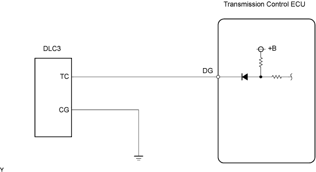
Terminals TC and CG are located in the DLC3. When performing [Clamp Position Adjustment] and [Initialization and Learning] without using an intelligent tester, connecting terminals TC and CG is necessary. If the TC terminal circuit is open, these calibration procedures cannot be performed without using an intelligent tester.
WIRING DIAGRAM
INSPECTION PROCEDURE
PROCEDURE
-
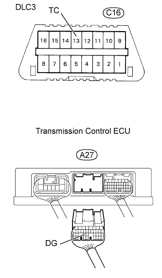
CHECK HARNESS AND CONNECTOR (TRANSMISSION CONTROL ECU - DLC3)
-
Disconnect the transmission control ECU connector.
-
Check the resistance.
Standard Resistance Tester Connections Specified Conditions DG (A27-25) - TC (C16-13) Below 1 Ω DG (A27-25) - Body ground 10 kΩ or higher -
Reconnect the transmission control ECU connector.
NG 
REPAIR OR REPLACE HARNESS OR CONNECTOR
OK 
-
-
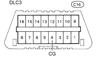
CHECK HARNESS AND CONNECTOR (DLC3 - BDY GROUND)
-
Check the resistance.
Standard Resistance Tester Connections Specified Conditions CG (C16-4) - Body ground Below 1 Ω
NG
REPAIR OR REPLACE HARNESS OR CONNECTOR
OK 
REPLACE TRANSMISSION CONTROL ECU ASSEMBLY
-