MULTI-MODE MANUAL TRANSAXLE SYSTEM Multi-Mode Manual Transmission Warning Light Circuit
DESCRIPTION
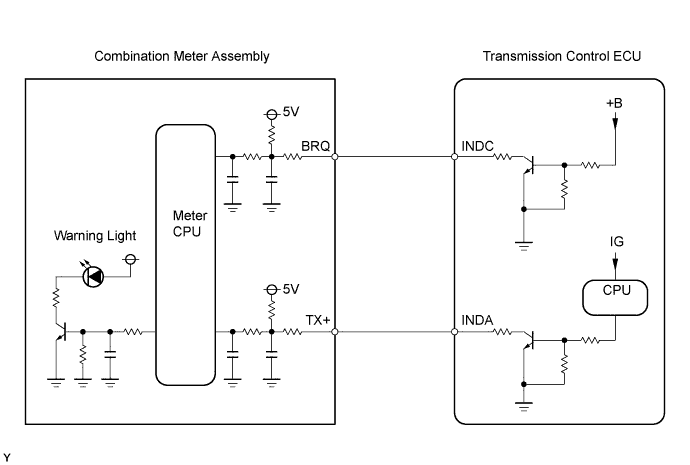
The combination meter interprets the multi-mode manual transmission system condition through the information from the INDC and INDA circuits, and if necessary, illuminates (blinks) the multi-mode manual transmission warning light.
-
INDC Terminal Circuit:
The battery voltage is constantly supplied to the INDC circuit. If the INDC circuit is open, the combination meter detects a malfunction in the circuit and illuminates the multi-mode manual transmission warning light. The INDC circuit is used to send the multi-mode manual transmission warning light signal to the combination meter when the ignition switch is off.
-
INDA Terminal Circuit:
Power is supplied to the INDA circuit when the ignition switch is on. While the ignition switch is on, the combination meter controls the multi-mode manual transmission warning light ON/OFF condition according to the signal from the INDA circuit. The INDA circuit is used to send the signals of the multi-mode manual transmission warning light and shift position indicator.
The contents of signals from the INDC and INDA circuits, and the status of the multi-mode manual transmission warning light and indicator are shown in the table below.
| INDA circuit state (at combination meter) | Normal | Inconsistent signal input (3 seconds or more) | Interrupted signal input (3 seconds or more) | |||
| INDC circuit (at combination meter) | Normal | +B short or open | Normal | +B short or open | Normal | +B short or open |
| LCD Indication *1 |
ON depends on communication signal |
ON depends on communication signal |
OFF | OFF | OFF | OFF |
| Multi-mode manual transmission warning light | ON depends on communication signal |
ON depends on communication signal |
ON | ON | ON | ON |
*1: When the LCD indication is ON, the number or letter segments come on.
| INDA circuit state (at combination meter) | Normal | Inconsistent signal input (3 seconds or more) | Interrupted signal input (3 seconds or more) | |||
| INDC circuit (at combination meter) | Normal | +B short or open | Normal | +B short or open | Normal | +B short or open |
| LCD Indication *1 |
ON depends on communication signal |
ON depends on communication signal |
OFF | OFF | OFF | OFF |
| Multi-mode manual transmission warning light | ON depends on communication signal |
ON depends on communication signal |
ON | ON | OFF | ON |
*1: When the LCD indication is ON, the number or letter segments come on.
WIRING DIAGRAM
INSPECTION PROCEDURE
Tech Tips
Check that the multi-mode manual transmission warning light and shift position indicator come on.
Under normal condition, the shift position indicator indicates the current gear position while the ignition switch is ON, and the multi-mode manual transmission warning light comes on for bulb check for approximately 5 seconds when the ignition switch is turned from OFF to ON.
If the shift position indicator does not come on, the INDA circuit may be malfunctioning. If the multi-mode manual transmission warning light does not come on, the INDA and/or INDC circuits may be malfunctioning.
PROCEDURE
-
CHECK HARNESS AND CONNECTOR (TRANSMISSION CONTROL ECU - COMBINATION METER)
-
Disconnect the transmission control ECU connector.
-
Disconnect the combination meter assembly connector.
-
Check the resistance.
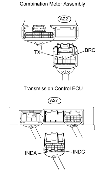
Standard Resistance Tester Connections Specified Conditions INDC (A27-29) - BRQ (A22-4) Below 1 Ω INDA (A27-31) - TX+ (A22-5) Below 1 Ω INDC (A27-29) - Body ground 10 kΩ or higher INDA (A27-31) - Body ground 10 kΩ or higher -
Reconnect the transmission control ECU connector.
-
Reconnect the combination meter assembly connector.
NG 
REPAIR OR REPLACE HARNESS OR CONNECTOR
OK 
-
-
INSPECT COMBINATION METER ASSEMBLY
-
Measure the voltage between the terminal of combination meter connector and the body ground.
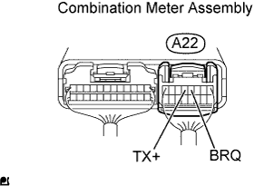
Standard Voltage Tester Connections Conditions Specified Conditions TX+ (A22-5) - Body ground Ignition switch OFF Approximately 3.64 V TX+ (A22-5) - Body ground Ignition switch ON Approximately 1.44 V BRQ (A22-4) - Body ground Always Approximately 1.44 V
NG
INSPECT METER / GAUGE SYSTEM
OK 
PROCEED TO NEXT CIRCUIT INSPECTION SHOWN IN PROBLEM SYMPTOMS TABLE
-