MULTI-MODE MANUAL TRANSAXLE SYSTEM Shift Lock Solenoid Circuit
DESCRIPTION
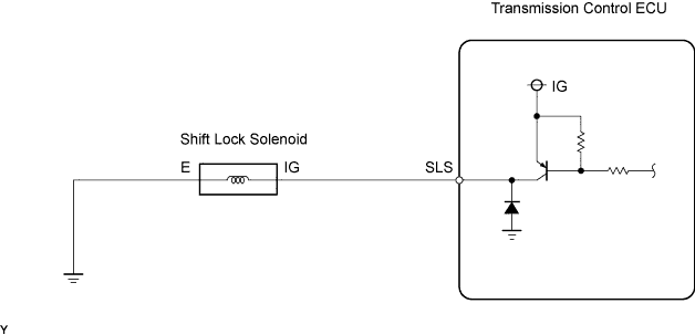
The shift lock solenoid is built into the shift lever assembly. When the ignition switch is turned to OFF, or when the shift lever is in the N position without depressing the brake pedal although the ignition switch is turned to ON, the shift lock solenoid restricts the shift lever movement.
The transmission control ECU sends the shift lock cancellation signal to the shift lock solenoid to cancel the shift lock when the multi-mode manual transmission system conditions are satisfied.
WIRING DIAGRAM
INSPECTION PROCEDURE
PROCEDURE
-
INSPECT SHIFT LOCK SOLENOID
-
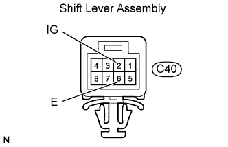
Disconnect the shift lever assembly connector.
-
Measure the shift lock solenoid resistance.
Standard Resistance Tester Connections Specified Conditions IG (C40-2) - E (C40-6) 30 to 35 Ω at 20°C (68°F)
NG 
REPLACE SHIFT LOCK SOLENOID
OK 
-
-
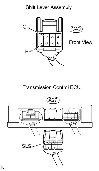
CHECK HARNESS AND CONNECTOR (SHIFT LOCK SOLENOID - TRANSMISSION CONTROL ECU, BODY GROUND)
-
Disconnect the shift lever assembly connector.
-
Disconnect the transmission control ECU connector.
-
Check the resistance.
Standard Resistance Tester Connections Specified Conditions SLS (A27-5) - IG (C40-2) Below 1 Ω E (C40-6) - Body ground Below 1 Ω SLS (A27-5) - Body ground 10 kΩ or higher -
Reconnect the transmission control ECU connector.
-
Reconnect the shift lever assembly connector.
NG
REPAIR OR REPLACE HARNESS OR CONNECTOR
OK
-
-
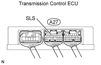
INSPECT TRANSMISSION CONTROL ECU ASSEMBLY
-
Turn the ignition switch to ON.
-
Measure the voltage between the terminal of the transmission control ECU and the body ground when the brake pedal is operated.
Standard Voltage Pedal Conditions Tester Connections Specified Conditions Brake pedal depressed SLS (A27-5) - Body ground 10 to 14 V Brake pedal released SLS (A27-5) Body ground Below 1 V
NG
REPLACE TRANSMISSION CONTROL ECU ASSEMBLY
OK 
PROCEED TO NEXT CIRCUIT INSPECTION SHOWN IN PROBLEM SYMPTOMS TABLE
-