MULTI-MODE MANUAL TRANSAXLE SYSTEM IG Signal Circuit
DESCRIPTION
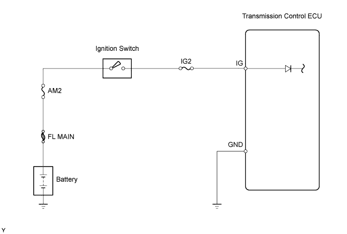
When the ignition switch is turned to ON, the battery voltage is applied to terminal IG of the transmission control ECU. Power is supplied to the transmission control ECU via terminals +B and IG. The transmission control ECU interprets the ignition switch condition through the potential at the IG terminal.
WIRING DIAGRAM
INSPECTION PROCEDURE
PROCEDURE
-
READ VALUE USING INTELLIGENT TESTER
-
Connect the intelligent tester to the DLC3.
-
Turn the ignition switch to ON and turn the tester ON.
-
Select the following menu items: Powertrain / Multi-Mode M/T / Data List
-
Read the value.
Items
[Abbreviation]
Measurement Items: Display Normal Conditions Diagnostic Notes Ignition Signal
[Ignition Sig]
Ignition switch signal:
Open (OFF) or +B (ON)
+B: Ignition switch ON - OK [+B] is displayed in the item [Ignition Signal] when the ignition switch is turned to ON.
OK 
PROCEED TO NEXT CIRCUIT INSPECTION SHOWN ON PROBLEM SYMPTOMS TABLE
NG 
-
-
INSPECT TRANSMISSION CONTROL ECU ASSEMBLY
-
Disconnect the transmission control ECU connector.
-
Turn the ignition switch to ON.
-
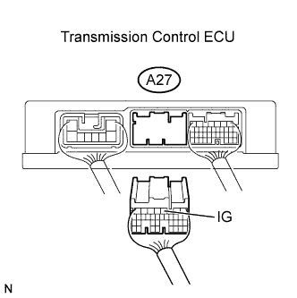
Measure the voltage between the terminal of transmission control ECU connector and the body ground.
Standard Voltage Tester Connections Ignition Switch Specified Conditions IG (A27-3) - Body ground OFF Below 1 V IG (A27-3) - Body ground ON 10 to 14 V -
Reconnect the transmission control ECU connector.
OK
REPLACE TRANSMISSION CONTROL ECU ASSEMBLY
NG
-
-
INSPECT IGNITION SWITCH ASSEMBLY
-
Disconnect the ignition switch connector.
-
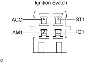
Check the ignition switch resistance.
Standard Resistance Switch Conditions Tester Connections Specified Conditions Lock 2 (AM1) - 1 (IG1) 10 kΩ or higher ON 2 (AM1) - 1 (IG1) Below 1 Ω -
Reconnect the ignition switch connector.
NG
REPLACE IGNITION SWITCH ASSEMBLY
OK 
REPAIR OR REPLACE HARNESS OR CONNECTOR
-