MULTI-MODE MANUAL TRANSAXLE SYSTEM Park / Neutral Position Switch Circuit
DESCRIPTION
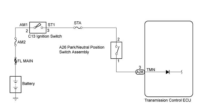
The park/neutral position switch detects the transmission gear Neutral position and sends a signal to the transmission control ECU. Based on the signal, the ECU detects the Neutral gear position. The engine starts when the ignition switch is turned to the ST position with the brake pedal depressed and the transmission gear in neutral.
WIRING DIAGRAM
INSPECTION PROCEDURE
Note
Inspect the fuses for circuits related to this system before performing the following inspection procedure.
PROCEDURE
-
INSPECT PARK/NEUTRAL POSITION SWITCH ASSEMBLY
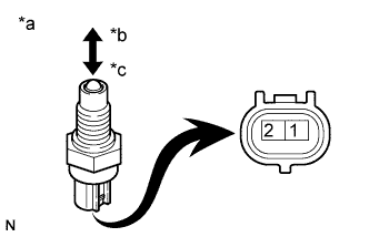
Text in Illustration *a Component without harness connected
(Park/neutral Position Switch Assembly)
*b Free *c Push
-
Remove the park/neutral position switch assembly.
-
Measure the park/neutral position switch assembly resistance.
Standard Resistance Tester Connection Switch Condition Specified Condition 1 - 2 Free 10 kΩ or higher 1 - 2 Pushed Below 1 Ω -
Reinstall the park/neutral position switch assembly.
NG 
REPLACE PARK/NEUTRAL POSITION SWITCH ASSEMBLY Click here
OK 
-
-
INSPECT TRANSMISSION CONTROL ECU ASSEMBLY
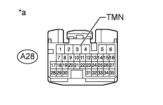
Text in Illustration *a Front view of wire harness connector
(to Transmission Control ECU)
-
Disconnect the transmission control ECU connector.
-
Turn the ignition switch to ON.
-
Confirm that the shift lever in N.
-
Measure the voltage between the terminal of transmission control ECU and the body ground when the ignition switch is turned to the ST position.
Standard Voltage Tester Connection Condition Specified Condition A28-3 (TMN) - Body ground Shift lever in N 11 to 14 V -
Turn the ignition switch off and reconnect the transmission control ECU connector.
-
Turn the ignition switch to ON.
-
Change the shift lever position to any position other than the N position while depressing the brake pedal.
-
Turn the ignition switch off and disconnect the transmission control ECU connector.
-
Turn the ignition switch to ON.
-
Measure the voltage between the terminal of transmission control ECU and the body ground when the ignition switch is turned to the ST position.
Standard Voltage Tester Connection Condition Specified Condition A28-3 (TMN) - Body ground Shift lever not in N Below 1 V -
Reconnect the transmission control ECU connector.
Result Result Proceed To NG A OK B
B
PROCEED TO NEXT SUSPECTED AREA SHOWN IN PROBLEM SYMPTOMS TABLE Click here
A
-
-
INSPECT IGNITION SWITCH
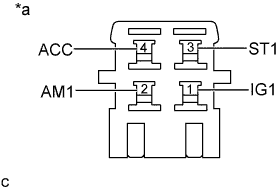
Text in Illustration *a Component without harness connected
(Ignition Switch)
-
Disconnect the C13 ignition switch connector.
-
Check the ignition switch resistance.
Standard Resistance Tester Connection Switch Condition Specified Condition 2 (AM1) - 1 (IG1)
2 (AM1) - 3 (ST1)
Lock 10 kΩ or higher 2 (AM1) - 1 (IG1) ON Below 1 Ω 2 (AM1) - 3 (ST1) ON 10 kΩ or higher 2 (AM1) - 1 (IG1) ST Below 1 Ω 2 (AM1) - 3 (ST1) ST Below 1 Ω -
Reconnect the C13 ignition switch connector.
NG
REPLACE IGNITION SWITCH
OK 
REPAIR OR REPLACE HARNESS OR CONNECTOR
-