MULTI-MODE MANUAL TRANSAXLE SYSTEM Starter Signal Circuit
DESCRIPTION
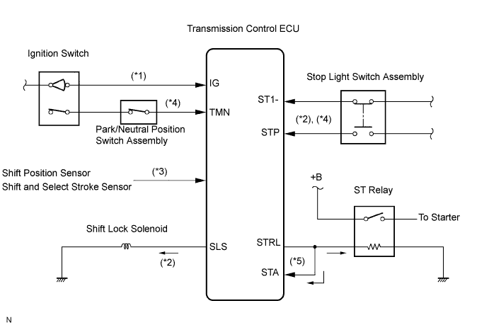
The ST relay that energizes the starter motor is operated by the transmission control ECU when the appropriate vehicle conditions are satisfied. If the brake pedal is not depressed or the transmission gear is not in neutral, the engine cannot be cranked. The following is the starter operation chart of the multi-mode manual transmission system.
-
The ignition switch is turned to ON. It activates the multi-mode manual transmission control ECU. (*1)
-
The transmission control ECU turns on the shift lock solenoid to release the shift lock while the brake pedal is depressed. (*2)
-
When the transmission gear is shifted into neutral, the park/neutral position switch located on the transmission housing is turned on. The transmission control ECU determines that the shift lever and transmission gear are in neutral (N position) using the shift lever position sensor and the shift and select stroke sensor. (*3)
-
The brake pedal is depressed and the ignition switch is turned to the ST position. The start signal from ignition switch is sent to the transmission control ECU via the neutral position switch. (*4)
-
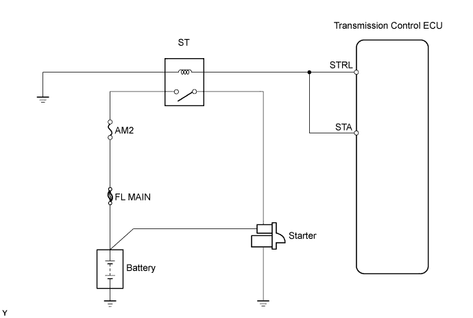
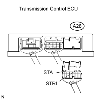
When above conditions are strictly observed, the transmission control ECU outputs starter relay drive signals from the STRL terminal to start the engine. The STA terminal of the transmission control ECU is used to monitor the STRL terminal output. (*5)
WIRING DIAGRAM
INSPECTION PROCEDURE
PROCEDURE
-
INSPECT ST RELAY
-
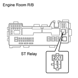
Remove the ST relay from the engine room R/B.
-
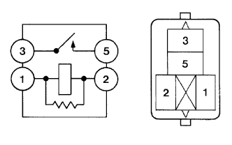
Check the ST relay resistance.
Standard Resistance Tester Connections Specified Conditions 3 - 5 10 kΩ or higher 3 - 5 Below 1 Ω
When battery voltage applied to terminals 1 and 2
-
Reinstall the ST relay.
NG 
REPLACE ST RELAY
OK 
-
-
READ VALUE USING INTELLIGENT TESTER
-
Connect an intelligent tester to the DLC3.
-
Turn the ignition switch to ON and turn the tester ON.
-
Select the following menu items: Powertrain / Multi-Mode M/T / Data List / STA Switch Signal
-
Check the value displayed on the tester when the ignition switch is turned to the ON and ST position.
Items
[Abbreviation]
Measurement Items: Display Normal Conditions Diagnostic Notes STA Switch Signal
[STA SW Sig]
STA signal:
ON or OFF
ON: During cranking - OK The STA Switch Signal is ON during cranking.
OK
PROCEED TO NEXT CIRCUIT INSPECTION SHOWN IN PROBLEM SYMPTOMS TABLE
NG
-
-
INSPECT TRANSMISSION CONTROL ECU ASSEMBLY
-
Turn the ignition switch to ON.
-
Confirm that the transmission gear is in neutral and the shift lever is in the N position.
-
Depress the brake pedal.
-
Measure the voltage between the transmission control ECU and the body ground when the ignition switch is turned to the ST position.
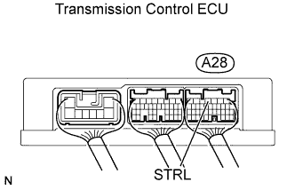
Standard Voltage Tester Connections Ignition Switch Position Specified Conditions STRL (A28-4) - Body ground ON Below 1 V STRL (A28-4) - Body ground ST 10 to 14 V
NG
PROCEED TO NEXT CIRCUIT INSPECTION SHOWN IN PROBLEM SYMPTOMS TABLE
OK
-
-
CHECK HARNESS AND CONNECTOR (TRANSMISSION CONTROL ECU - BATTERY, BODY GROUND)
-
Disconnect the transmission control ECU connector.
-
Remove the ST relay from the engine room R/B.
-
Check the resistance.
Standard Resistance Tester Connections Specified Conditions STRL (A28-4) - STA (A28-6) Below 1 Ω STRL (A28-4) - ST relay terminal 1 Below 1 Ω STRL (A28-4) - Body ground 10 kΩ or higher ST relay terminal 2 - Body ground Below 1 Ω ST relay terminal 3 - Starter terminal (B16-1) Below 1 Ω ST relay terminal 5 - Body ground 10 kΩ or higher -
Reconnect the transmission control ECU connector.
-
Reinstall the ST relay.
NG
REPAIR OR REPLACE HARNESS OR CONNECTOR
OK 
PROCEED TO NEXT CIRCUIT INSPECTION SHOWN IN PROBLEM SYMPTOMS TABLE
-