MULTI-MODE MANUAL TRANSAXLE SYSTEM, Diagnostic DTC:U0100

| DTC Code | DTC Name |
|---|---|
| U0100 | Lost Communication with ECM/PCM "A" |
DESCRIPTION
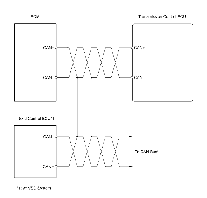
The transmission control ECU and ECM communicate with each other via the CAN communication line.
| DTC No. | DTC Detection Conditions | Trouble Areas |
|---|---|---|
| U0100 | No communication with the ECM (1 trip detection logic) |
|
WIRING DIAGRAM
INSPECTION PROCEDURE
Tech Tips
If the CAN communication malfunctions, the transmission control ECU cannot receive the current data from the ECM. In this case, the freeze frame data output from the transmission control ECU have not been updated so that it will not be useful information for the inspection procedure. However, reading the Data List as the first step of troubleshooting is effective to find malfunctions.
Note
In the table below, the values listed under Normal Conditions are for reference only. Do not depend solely on these reference values when deciding whether a part is faulty or not.
To check the Data List, perform the following procedure using the intelligent tester.
-
Warm up the engine.
-
Turn the ignition switch to OFF.
-
Connect the intelligent tester to the DLC3.
-
Turn the ignition switch to ON and turn the tester ON.
-
Following the display on the tester, read the Data List.
| Items [Abbreviation] |
Measurement Items: Display | Normal Conditions | Diagnostic Notes |
|---|---|---|---|
| Calculated Engine Load [Calc E/G Load] |
Calculated load by ECM: Min.: 0 %, Max.: 100 % |
1.5 to 3.0 %: Idling 2.0 to 10.0 %: Running without load (2,500 rpm) |
- |
| Engine Coolant Temperature [Coolant Temp] |
Coolant temperature: Min.: -40°C , Max.: 215°C |
75 to 95°C (167 to 203°F): After engine warmed up |
|
| Backup Engine Speed [Bacup Engin Spd] |
Back-up engine speed: Min.: 0 rpm, Max.: 8,160 rpm |
0 rpm: Vehicle stopped Approximately same as tachometer reading: Vehicle running |
0 rpm displayed when malfunction in CAN communication |
| Accelerator Pedal Angle [Accel Pedl Angl] |
Accelerator pedal angle Min.: 0 %, Max.: 100 % |
0 %: Accelerator pedal released | 0 % displayed when malfunction in CAN communication |
Note
In ECM replacement, perform the electronic throttle learning after installing the ECM.
PROCEDURE
-
CHECK DTC OUTPUT
-
Connect the intelligent tester to the DLC3.
-
Turn the ignition switch to ON and turn the tester ON.
-
Select the following menu items: Powertrain / Multi-Mode M/T / DTC.
-
Read DTCs.
Result Display (DTC Output) Proceed To U0100 (w/o VSC System) A U0100 (w/ VSC System) B DTC not output C
B 
INSPECT CAN COMMUNICATION SYSTEM
C
CHECK FOR INTERMITTENT PROBLEMS
A 
-
-
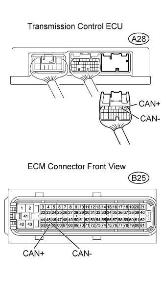
CHECK HARNESS AND CONNECTOR (TRANSMISSION CONTROL ECU - ECM)
-
Disconnect the ECM connector.
-
Disconnect the transmission control ECU connector.
-
Check the resistance.
Standard Resistance Tester Connections Specified Conditions CAN+ (A28-1) - CAN+ (B25-64) Below 1 Ω CAN- (A28-2) - CAN- (B25-45) Below 1 Ω CAN+ (A28-1) - Body ground 10 kΩ or higher CAN- (A28-2) - Body ground 10 kΩ or higher -
Reconnect the ECM connector.
-
Reconnect the transmission control ECU connector.
NG
REPAIR OR REPLACE HARNESS OR CONNECTOR
OK
-
-
REPLACE TRANSMISSION CONTROL ECU ASSEMBLY
-
Replace the transmission control ECU.
CAUTION:
Replace the transmission control ECU with a transmission control ECU from a normally functioning vehicle of the same model.
NEXT
-
-
CHECK DTC OUTPUT
-
Connect the intelligent tester to the DLC3.
-
Turn the ignition switch to ON and turn the tester ON.
-
Clear the DTC.
-
Turn the ignition switch to OFF and turn the tester OFF.
-
Start the engine and turn the tester ON.
-
Select the following menu items: Powertrain / Multi-Mode M/T / DTC.
-
Read DTCs.
Result Display (DTC Output) Proceed To U0100 A DTC not output B
B
REPLACE TRANSMISSION CONTROL ECU ASSEMBLY
A 
REPLACE ECM
-