MULTI-MODE MANUAL TRANSAXLE SYSTEM, Diagnostic DTC:P0920

| DTC Code | DTC Name |
|---|---|
| P0920 | Gear Shift Forward Actuator Circuit |
DESCRIPTION
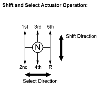
The shift and select actuator is operated by the transmission control ECU and changes the transmission gear by the shift and select lever shaft movement. An electric motor (shift motor) moves the shift and select lever shaft to shift direction, and the shift stroke sensor, which is mounted on the shift and select actuator assembly, detects the shift position. The transmission control ECU monitors the electrical current and shift motor output terminal voltage, and detects malfunctions in the shift motor circuit.
| DTC No. | DTC Detection Conditions | Trouble Areas |
|---|---|---|
| P0920 | The transmission control ECU detects the following conditions: (1 trip detection logic)
|
|
| P0920 | The transmission control ECU detects the following conditions: (1 trip detection logic)
|
|
| P0920 | The transmission control ECU detects the following conditions: (1 trip detection logic)
|
|
-
*1: A short between the shift motor circuit and the body ground is suspected.
-
*2: A short between the shift motor circuit and the +B circuit is suspected.
-
*3: An open in the shift motor circuit is suspected. When the motor current does not flow to the ECU terminals despite the ECU ordering the shift motor to operate, the ECU sets the DTC.
-
*4: An open in the shift motor circuit is suspected. When the difference is more than the threshold despite the ECU not ordering the shift motor to operate, the ECU sets the DTC.
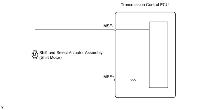
WIRING DIAGRAM
INSPECTION PROCEDURE
Note
-
In clutch actuator assembly replacement, perform Clamp Position Adjustment before removing the actuator.
-
In shift stroke sensor or shift and select actuator assembly replacement, perform the [Initialization and Learning] procedure Click here and [Synchronization Position Calibration] procedure Click here after installing the sensor or actuator assembly. If the sensor or actuator is installed without performing [Initialization and Learning] and [Synchronization Position Calibration], it may cause driving performance degradation or system component breakage.
PROCEDURE
-
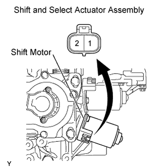
INSPECT SHIFT AND SELECT ACTUATOR ASSEMBLY
-
Disconnect the shift motor connector.
-
Measure the shift motor resistance.
Standard Resistance Tester Connections Specified Conditions 1 - 2 0.1 to 100 Ω -
Reconnect the shift motor connector.
NG 
REPLACE SHIFT AND SELECT ACTUATOR ASSEMBLY
OK 
-
-
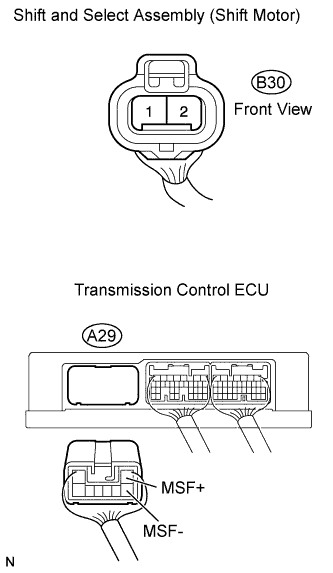
CHECK HARNESS AND CONNECTOR (SHIFT AND SELECT ACTUATOR - TRANSMISSION CONTROL ECU)
-
Disconnect the shift motor connector.
-
Disconnect the transmission control ECU connector.
-
Check the resistance.
Standard Resistance Tester Connections Specified Conditions MSF- (A29-3) - (B30-1) Below 1 Ω MSF+ (A29-1) - (B30-2) Below 1 Ω MSF- (A29-3) - Body ground 10 kΩ or higher MSF+ (A29-1) - Body ground 10 kΩ or higher -
Reconnect the shift motor connector.
-
Reconnect the transmission control ECU connector.
NG
REPAIR OR REPLACE HARNESS OR CONNECTOR
OK 
REPLACE TRANSMISSION CONTROL ECU ASSEMBLY
-