MULTI-MODE MANUAL TRANSAXLE SYSTEM, Diagnostic DTC:P0915, P0916, P0917

| DTC Code | DTC Name |
|---|---|
| P0915 | Gear Shift Position Circuit Range / Performance |
| P0916 | Gear Shift Position Circuit Low |
| P0917 | Gear Shift Position Circuit High |
DESCRIPTION
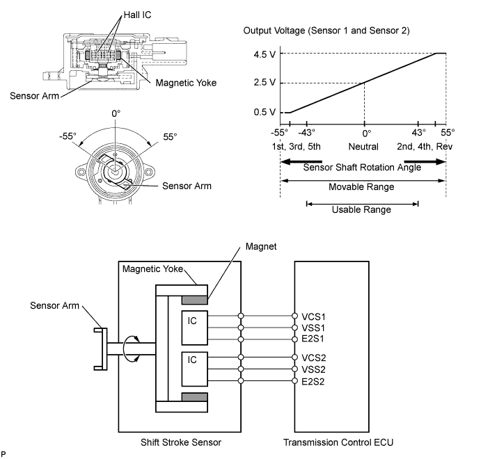
The shift stroke sensor is mounted on the shift and select actuator, and detects the shift position of the shift and select lever shaft. The sensor consists of a sensor arm, magnetic yoke and 2 Hall-ICs. This sensor is a non-contact type, and uses Hall-effect elements (Hall-ICs: main and sub), in order to yield accurate signals.
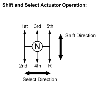
When the shift and select actuator is operating in the shift direction, the magnetic yoke that is coaxially positioned on the sensor arm is rotated and the magnet position changes. The hall-ICs convert the magnet position change into the voltage signal and send it to the transmission control ECU. The transmission control ECU judges the shift motor operating condition (whether the gear is shifted to 1st, 3rd and 5th or 2nd, 4th and Reverse) based on the signal from the shift stroke sensor.
The main and sub circuits in the shift stroke sensor have the same output characteristics.
The sensor construction and operation of the shift stroke sensor are basically the same as those of the clutch stroke sensor.
| DTC No. | DTC Detection Conditions | Trouble Areas |
|---|---|---|
| P0915 | Deviation between sensor signal 1 (main) and sensor signal 2 (sub) is 2.0 mm (0.078 in.) or more for 1.0 second or more (1 trip detection logic) |
|
| P0916 | Shift stroke sensor (main) signal voltage is 0.2 V or less for 0.5 seconds or more (1 trip detection logic) |
|
| P0916 | Shift stroke sensor (sub) signal voltage is 0.2 V or less for 0.5 seconds or more (1 trip detection logic) |
|
| P0917 | Shift stroke sensor (main) signal voltage is 4.8 V or more for 0.5 seconds or more (1 trip detection logic) |
|
| P0917 | Shift stroke sensor (sub) signal voltage is 4.8 V or more for 0.5 seconds or more (1 trip detection logic) |
|
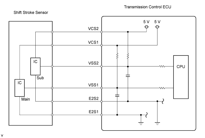
WIRING DIAGRAM
INSPECTION PROCEDURE
Note
In shift stroke sensor replacement, perform [Initialization and Learning] Click here and [Synchronization Position Calibration] Click here after installing the sensor.
If the sensor is installed without performing [Initialization and Learning] and [Synchronization Position Calibration], it may cause driving performance degradation or system component breakage.
Tech Tips
When only DTC P0915 is set, replace the shift stroke sensor.
PROCEDURE
-
READ OUTPUT DTC
-
Connect the intelligent tester to the DLC3.
-
Turn the ignition switch to ON and turn the tester ON.
-
Select the following menu items: Powertrain / Multi-Mode M/T / DTC.
-
Read DTCs.
Result Display (DTC Output) Proceed To P0915, P0916 and/or P0917 A Only P0915 B
B 
REPLACE SHIFT STROKE SENSOR
A 
-
-
READ VALUE USING INTELLIGENT TESTER
-
Connect the intelligent tester to the DLC3.
-
Turn the ignition switch to ON and the tester ON.
-
Select the following menu items: Powertrain / Multi-Mode M/T / Data List / Shift Position (Current).
Items
[Abbreviation]
Measurement Items: Display Normal Conditions Diagnostic Notes Shift Position (Current)
[Shift Pos-Cur]
Current shift position:
Min.: 0 mm, Max.: 31.999 mm
5.0 mm (0.20 in.) to 31.9 mm (1.25 in.) Current shift position value displayed (1st, 3rd, 5th, or Neutral, or 2nd, 4th, Reverse) OK The value on the tester is within the normal range.
OK 
INSPECT SHIFT STROKE SENSOR (SUB) Click here
NG
-
-
INSPECT SHIFT STROKE SENSOR (MAIN)
-
Remove the shift stroke sensor.
-
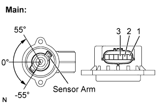
Measure the voltage between the terminals of the shift stroke sensor connector (main).
-
Prepare 3 dry cell batteries (1.5 V) and 2 leads for connecting the batteries and the sensor.
-
Connect the batteries in series.
-
Connect the positive battery terminal to sensor terminal 3, and the negative battery terminal to sensor terminal 2.
-
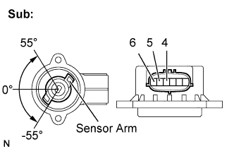
Check the voltage between terminals 1 and 2.
Standard Voltage (combined dry cell battery voltage of 4.5 V) Sensor Angle Terminal (1-2) Output Voltage 55° Approximately 4.05 V 0° Approximately 2.25 V -55° Approximately 0.45 V Reference Voltage (combined dry cell battery voltage of 5.0 +- 0.3 V) Sensor Angle Terminal (1-2) Output Voltage 55° Approximately 4.5 V 0° Approximately 2.5 V -55° Approximately 0.5 V Note
-
Do not apply more than 6 V
-
Do not use a sensor which has been dropped.
-
-
-
Reinstall the shift stroke sensor Click here.
-
Perform [Initialization and Learning] Click here and [Synchronization Position Calibration] Click here.
NG
REPLACE SHIFT STROKE SENSOR
OK
-
-
INSPECT SHIFT STROKE SENSOR (SUB)
-
Remove the shift stroke sensor.
-
Measure the voltage between the terminals of the shift stroke sensor connector (sub).
-
Prepare 3 dry cell batteries (1.5 V) and 2 leads for connecting the batteries and the sensor.
-
Connect the batteries in series.
-
Connect the positive battery terminal to sensor terminal 6, and the negative battery terminal to sensor terminal 5.
-
Check the voltage between terminals 4 and 5.
Standard Voltage (combined dry cell battery voltage of 4.5 V) Sensor Angle Terminal (4-5) Output Voltage 55° Approximately 4.05 V 0° Approximately 2.25 V -55° Approximately 0.45 V Reference Voltage (combined dry cell battery voltage of 5.0 +- 0.3 V) Sensor Angle Terminal (4-5) Output Voltage 55° Approximately 4.5 V 0° Approximately 2.5 V -55° Approximately 0.5 V Note
-
Do not apply more than 6 V
-
Do not use a sensor which has been dropped.
-
-
-
Reinstall the shift stroke sensor Click here.
-
Perform [Initialization and Learning] Click here and [Synchronization Position Calibration] Click here.
NG
REPLACE SHIFT STROKE SENSOR
OK
-
-
CHECK HARNESS AND CONNECTOR (SHIFT STROKE SENSOR - TRANSMISSION CONTROL ECU)
-
Disconnect the shift stroke sensor connector.
-
Disconnect the transmission control ECU connector.
-
Check the resistance.
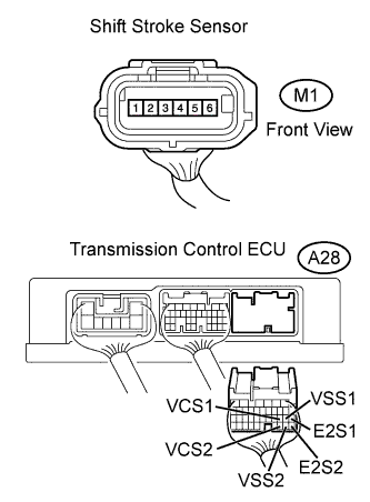
Standard Resistance Tester Connections Specified Conditions VCS2 (A28-30) - (A25-6) Below 1 Ω VSS2 (A28-29) - (A25-4) Below 1 Ω E2S2 (A28-28) - (A25-5) Below 1 Ω VCS1 (A28-19) - (A25-3) Below 1 Ω VSS1 (A28-18) - (A25-1) Below 1 Ω E2S1 (A28-17) - (A25-2) Below 1 Ω VCS2 (A28-30) - Body ground 10 kΩ or higher VSS2 (A28-29) - Body ground 10 kΩ or higher E2S2 (A28-28) - Body ground 10 kΩ or higher VCS1 (A28-19) - Body ground 10 kΩ or higher VSS1 (A28-18) - Body ground 10 kΩ or higher E2S1 (A28-17) - Body ground 10 kΩ or higher -
Reconnect the shift stroke sensor connector.
-
Reconnect the transmission control ECU connector.
NG
REPAIR OR REPLACE HARNESS OR CONNECTOR
OK 
REPLACE TRANSMISSION CONTROL ECU ASSEMBLY
-