MULTI-MODE MANUAL TRANSAXLE SYSTEM, Diagnostic DTC:P0909

| DTC Code | DTC Name |
|---|---|
| P0909 | Gate Select Control Error |
DESCRIPTION
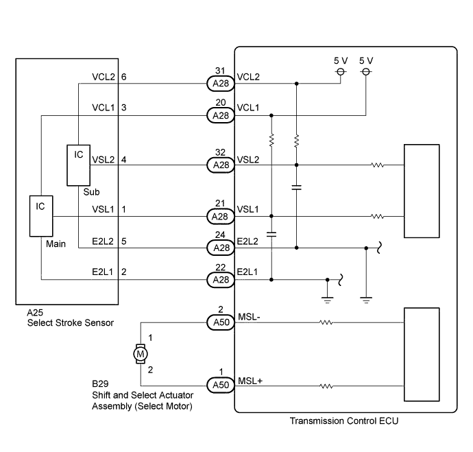
In the multi-mode manual transaxle system, the transaxle gear is shifted up and down by the transmission control ECU using a shift and select actuator. The shift and select actuator assembly consists of two motors (shift motor and select motor), stroke sensors (shift stroke sensor and select stroke sensor) and gears which move the shift and select lever shaft. The select motor moves the shift and select lever shaft in the select direction in accordance with the signal from the transmission control ECU.
This DTC is set in accordance with the stroke speed of the shift and select actuator or the difference between the target select position and the actual select position. Therefore, if malfunctions occur in the select stroke sensor or the select motor circuit, the DTCs relating to the sensor or motor circuit open/short (DTC P0905, P0906, P0907 and/or P0910) are set before this DTC is set.
| DTC No. | DTC Detection Condition | Trouble Area |
|---|---|---|
| P0909 | The transmission control ECU detects the following conditions simultaneously for 2.0 seconds: (1-trip detection logic)
|
|
WIRING DIAGRAM
INSPECTION PROCEDURE
Note
In select stroke sensor or shift and select actuator assembly replacement, perform the [Initialization and Learning] procedure Click here and [Synchronization Position Calibration] procedure Click here after installing the sensor or actuator assembly. If the sensor or actuator is installed without performing [Initialization and Learning] and [Synchronization Position Calibration], it may cause driving performance degradation or system component breakage.
Tech Tips
If the symptom still occurs even after checking the shift heads and shift fork shafts for dirt, wear, and defects and replacing the defective parts, replace the transmission control ECU.
PROCEDURE
-
PERFORM ACTIVE TEST USING INTELLIGENT TESTER (TARGET GEAR POSITION CONTROL)
-
Remove the shift and select actuator assembly Click here.
-
Connect the shift and select actuator assembly connector.
-
Connect the intelligent tester to the DLC3.
-
Turn the ignition switch to ON.
-
Turn the tester on.
-
Enter the following menus: Powertrain / Multi-Mode M/T / Active Test / Target Gear Position Control.
OK Shift and select actuator moves smoothly in accordance with the tester operation.
NG 
REPLACE SHIFT AND SELECT ACTUATOR ASSEMBLY Click here
OK 
-
-
INSPECT SELECT STROKE SENSOR
-
Remove the select stroke sensor.
-
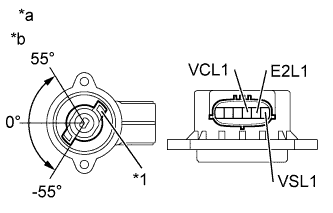
Text in Illustration *1 Sensor Arm *a Component without harness connected
(Select Stroke Sensor)
*b Main Measure the voltage between the terminals of the select stroke sensor connector (main).
-
Prepare 3 dry cell batteries (1.5 V) and 2 leads for connecting the batteries and the sensor.
-
Connect the batteries in series.
-
Connect the positive battery terminal to sensor terminal 3 (VCL1), and the negative battery terminal to sensor terminal 2 (E2L1).
-
Measure the voltage according to the value(s) in the table below.
Standard Voltage (combined dry cell battery voltage of 4.5 V) Tester Connection Condition
(Sensor Angle)
Specified Condition 1 (VSL1) - 2 (E2L1) 55° Approximately 4.05 V 0° Approximately 2.25 V -55° Approximately 0.45 V Reference Voltage (combined dry cell battery voltage of 5.0 +/- 0.3 V) Tester Connection Condition
(Sensor Angle)
Specified Condition 1 (VSL1) - 2 (E2L1) 55° Approximately 4.5 V 0° Approximately 2.5 V -55° Approximately 0.5 V
-
-
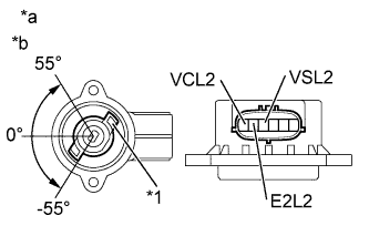
Text in Illustration *1 Sensor Arm *a Component without harness connected
(Select Stroke Sensor)
*b Sub Measure the voltage between the terminals of the select stroke sensor connector (Sub).
-
Connect the positive battery terminal to sensor terminal 6 (VCL2), and the negative battery terminal to sensor terminal 5 (E2L2).
-
Measure the voltage according to the value(s) in the table below.
Standard Voltage (combined dry cell battery voltage of 4.5 V) Tester Connection Condition
(Sensor Angle)
Specified Condition 4 (VSL2) - 5 (E2L2) 55° Approximately 4.05 V 0° Approximately 2.25 V -55° Approximately 0.45 V Reference Voltage (combined dry cell battery voltage of 5.0 +/- 0.3 V) Tester Connection Condition
(Sensor Angle)
Specified Condition 4 (VSL2) - 5 (E2L2) 55° Approximately 4.5 V 0° Approximately 2.5 V -55° Approximately 0.5 V Note
-
Do not apply more than 6 V
-
Do not use a sensor which has been dropped.
-
-
NG
OK
-
-
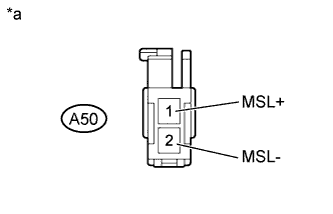
INSPECT TRANSMISSION CONTROL ECU (MSL TERMINAL VOLTAGE)
-
Turn the ignition switch to ON.
-
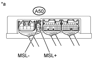
Text in Illustration *a Component with harness connected
(Transmission Control ECU)
Measure the voltage according to the value(s) in the table below.
Standard Voltage Tester Connection Switch Condition Specified Condition A50-1 (MSL+) - Body ground Ignition switch ON 4.0 to 7.0 V A50-2 (MSL-) - Body ground Ignition switch ON 4.0 to 7.0 V -
Turn the ignition switch off.
NG
CHECK TERMINAL CONDITION (TRANSMISSION CONTROL ECU) Click here
OK
-
-
INSPECT TRANSAXLE ASSEMBLY
-
Remove the transaxle assembly Click here.
-
Check for dirt, wear and defects in the gear shift mechanical system (synchronizer rings, shift forks, hub sleeves, etc.).
OK No defective parts in the transaxle assembly.
NG 
REPAIR OR REPLACE DEFECTIVE PART IN TRANSAXLE ASSEMBLY
OK
-
-
REPLACE TRANSMISSION CONTROL ECU
-
Replace the transmission control ECU Click here.
NEXT
-
-
PERFORM INITIALIZATION
-
Perform the initialization and learning for multi-mode manual transaxle system Click here.
NEXT 
END
-
-
CHECK TERMINAL CONDITION (TRANSMISSION CONTROL ECU)
-
Disconnect the A50 transmission control ECU connector.
-
Check the connections of the transmission control ECU connector.
OK The transmission control ECU and wire harness connectors and connector terminals are connected securely and are not bent, rusted, or damaged.
NG
CONNECT CORRECTLY
OK
-
-
INSPECT SELECT MOTOR CIRCUIT
-
Text in Illustration *a Front view of wire harness connector
(to Transmission Control ECU)
Measure the resistance according to the value(s) in the table below.
Standard Resistance Tester Connection Switch Condition Specified Condition A50-1 (MSL+) - A50-2 (MSL-) Always 0.1 to 100 Ω A50-1 (MSL+) - Body ground Always 10 kΩ or higher A50-2 (MSL-) - Body ground Always 10 kΩ or higher
NG
CHECK TERMINAL CONDITION (SELECT MOTOR) Click here
OK
-
-
REPLACE TRANSMISSION CONTROL ECU
-
Replace the transmission control ECU Click here.
NEXT
-
-
PERFORM INITIALIZATION
-
Perform the initialization and learning for multi-mode manual transaxle system Click here.
NEXT
END
-
-
CHECK TERMINAL CONDITION (SELECT MOTOR)
-
Disconnect the B29 select motor connector.
-
Check the connections of the select motor connector.
OK The select motor and wire harness connectors and connector terminals are connected securely and are not bent, rusted, or damaged.
NG
CONNECT CORRECTLY
OK
-
-
CHECK HARNESS AND CONNECTOR (TRANSMISSION CONTROL ECU - SELECT MOTOR)
-
Measure the resistance according to the value(s) in the table below.
Standard Resistance Tester Connection Switch Condition Specified Condition A50-1 (MSL+) - B29-2 Always Below 1 Ω A50-1 (MSL-) - B29-1 Always Below 1 Ω A50-1 (MSL+) or B29-2 - Body ground Always 10 kΩ or higher A50-2 (MSL-) or B29-1 - Body ground Always 10 kΩ or higher
NG
REPAIR OR REPLACE HARNESS OR CONNECTOR
OK
-
-
INSPECT SHIFT AND SELECT ACTUATOR ASSEMBLY (SELECT MOTOR)
-
Disconnect the B29 select motor connector.
-
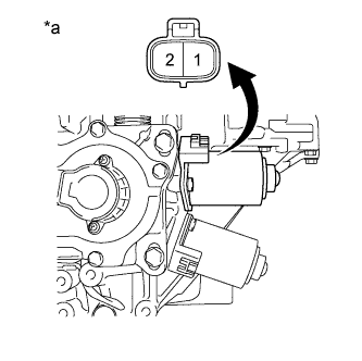
Text in Illustration *a Component without harness connected
(Shift and Select Actuator Assembly (Select Motor))
Measure the resistance according to the value(s) in the table below.
Standard Resistance Tester Connection Condition Specified Condition 1 - 2 Always 0.1 to 100 Ω 1 - Body ground Always 10 kΩ or higher 2 - Body ground Always 10 kΩ or higher
NG
REPLACE SHIFT AND SELECT ACTUATOR ASSEMBLY Click here
OK
CHECK INTERMITTENT PROBLEMS Click here
-
-
REPLACE SHIFT AND SELECT ACTUATOR ASSEMBLY
-
Replace the shift and select actuator assembly Click here.
NEXT
-
-
PERFORM INITIALIZATION
-
Perform the initialization and learning for multi-mode manual transaxle system Click here.
NEXT
END
-
-
REPLACE SELECT STROKE SENSOR
-
Replace the select stroke sensor Click here.
NEXT
-
-
PERFORM INITIALIZATION
-
Perform the initialization and learning for multi-mode manual transaxle system Click here.
NEXT
END
-