MULTI-MODE MANUAL TRANSAXLE SYSTEM, Diagnostic DTC:P0909

| DTC Code | DTC Name |
|---|---|
| P0909 | Gate Select Control Error |
DESCRIPTION
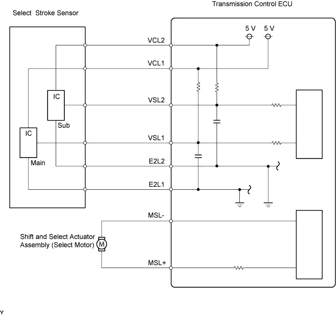
In the multi-mode manual transmission system, the transmission gear is shifted up and down by the transmission control ECU using a shift and select actuator. The shift and select actuator assembly consists of two motors (shift motor and select motor), stroke sensors (shift stroke sensor and select stroke sensor) and gears which moves the shift and select lever shaft. The select motor moves the shift and select lever shaft to the select direction in accordance with the signal from the transmission control ECU.
This DTC is set in accordance with the stroke speed of the shift and select actuator or the difference between the target select position and the actual select position. Therefore, if malfunctions occur in the select stroke sensor or the select motor circuit, the DTCs relating to the sensor or motor circuit open/short (DTC P0905, P0906, P0907 and/or P0910) are set before this DTC is set.
| DTC No. | DTC Detection Conditions | Trouble Areas |
|---|---|---|
| P0909 | The transmission control ECU detects the following conditions simultaneously: (1 trip detection logic)
|
|
Tech Tips
*1: For the shift heads and shift fork shaft location, refer to MULTI-MODE MANUAL TRANSAXLE UNIT Click here.
WIRING DIAGRAM
INSPECTION PROCEDURE
Note
-
In clutch actuator assembly replacement, perform Clamp Position Adjustment before removing the actuator.
-
In select stroke sensor or shift and select actuator assembly replacement, perform the [Initialization and Learning] procedure Click here and [Synchronization Position Calibration] procedure Click here after installing the sensor or actuator assembly. If the sensor or actuator is installed without performing [Initialization and Learning] and [Synchronization Position Calibration], it may cause driving performance degradation or system component breakage.
Tech Tips
If the symptom still occurs even after checking the shift heads and shift fork shafts for dirt, wear, and defects and replacing the defective parts, replace the transmission control ECU.
PROCEDURE
-
CHECK OTHER DTC OUTPUT (IN ADDITION TO DTC P0909)
-
Connect the intelligent tester to the DLC3.
-
Turn the ignition switch to ON and turn the tester ON.
-
Select the following menu items: Powertrain / Multi-Mode M/T / DTC.
-
Read DTCs.
Result Display (DTC Output) Proceed To P0909 A P0909 and other DTCs B If DTC P0909 is detected together with DTC P0905, P0906, P0907, and/or P0910 (DTCs related to the select stroke sensor or shift and select actuator motor circuit open/short), troubleshoot those DTCs first.
B 
GO TO DTC CHART
A 
-
-
INSPECT TRANSMISSION CONTROL ECU ASSEMBLY
-
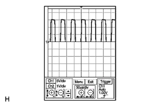
Check the shift and select actuator motor terminal output using an oscilloscope.
-
Connect the intelligent tester to the DLC3.
-
Turn the ignition switch to ON and turn the tester ON.
-
Clear the DTC after saving the recorded freeze frame data.
-
Turn the ignition switch to OFF within 2 seconds after clearing the DTC.
-
Connect the oscilloscope probes to the transmission control ECU terminals.
-
Check the waveform when the ignition switch is turned to ON and the shift lever position is changed from the N position to any other position.
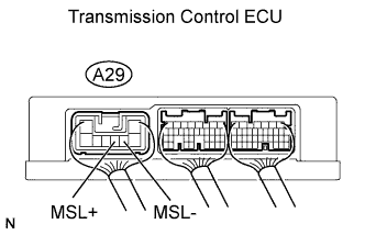
Tester Settings Items Contents Terminals MSL- (A29-4) - GND (A27-6)
MSL+ (A29-5) - GND (A27-6)
Gauge set 5 V/DIV, 50 μs/DIV Condition Ignition switch ON Standard Correct waveform shown in the illustration. Tech Tips
The waveform is displayed for several seconds until the DTC is set.
-
NG
REPLACE TRANSMISSION CONTROL ECU ASSEMBLY
OK
-
-
INSPECT TRANSMISSION CONTROL ECU ASSEMBLY
-
Remove the select stroke sensor from the shift and select actuator assembly.
-
Connect the select stroke sensor connector.
-
Turn the ignition switch to ON.
-
Check the voltage change between the terminals of the transmission control ECU connector when moving the sensor arm of the select stroke sensor.
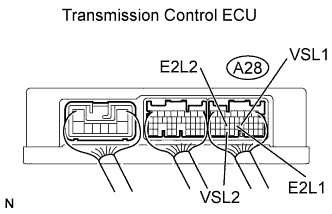
Standard Voltage Tester Connections Specified Conditions VSL1 (A28-21) - E2L1 (A28-22) Voltage changes in accordance with sensor arm position VSL2 (A28-32) - E2L2 (A28-24) Voltage changes in accordance with sensor arm position -
Reinstall the select stroke sensor Click here.
-
Perform [Initialization and Learning] Click here and [Synchronization Position Calibration] Click here
OK 
PERFORM ACTIVE TEST USING INTELLIGENT TESTER Click here
NG
-
-
INSPECT SELECT STROKE SENSOR
-
Remove the select stroke sensor.
-
Measure the voltage between the terminals of the select stroke sensor connector (main).
-
Prepare 3 dry cell batteries (1.5 V) and 2 leads for connecting the batteries and the sensor.
-
Connect the batteries in series.
-
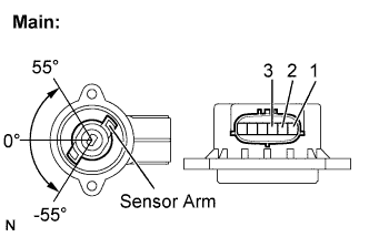
Connect the positive battery terminal to sensor terminal 3, and the negative battery terminal to sensor terminal 2.
-
Check the voltage between terminals 1 and 2.
Standard Voltage (combined dry cell battery voltage of 4.5 V) Sensor Angle Terminal (1-2) Output Voltage 55° Approximately 4.05 V 0° Approximately 2.25 V -55° Approximately 0.45 V Reference Voltage (combined dry cell battery voltage of 5.0 +- 0.3 V) Sensor Angle Terminal (1-2) Output Voltage 55° Approximately 4.5 V 0° Approximately 2.5 V -55° Approximately 0.5 V
-
-
Measure the voltage between the terminals of the select stroke sensor connector (sub).
-
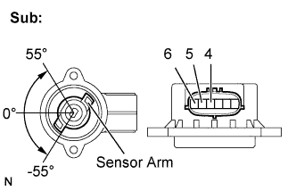
Connect the positive battery terminal to sensor terminal 6, and the negative battery terminal to sensor terminal 5.
-
Check the voltage between terminals 4 and 5.
Standard Voltage (combined dry cell battery voltage of 4.5 V) Sensor Angle Terminal (4-5) Output Voltage 55° Approximately 4.05 V 0° Approximately 2.25 V -55° Approximately 0.45 V Reference Voltage (combined dry cell battery voltage of 5.0 +- 0.3 V) Sensor Angle Terminal (4-5) Output Voltage 55° Approximately 4.5 V 0° Approximately 2.5 V -55° Approximately 0.5 V Note
-
Do not apply more than 6 V
-
Do not use a sensor which has been dropped.
-
-
-
Reinstall the select stroke sensor Click here.
-
Perform [Initialization and Learning] Click here and [Synchronization Position Calibration] Click here.
NG
REPLACE SELECT STROKE SENSOR
OK 
REPLACE TRANSMISSION CONTROL ECU ASSEMBLY
-
-
PERFORM ACTIVE TEST USING INTELLIGENT TESTER
-
Remove the clutch actuator Click here.
-
Remove the shift and select actuator.
-
Connect all the connectors to the clutch actuator and the shift and select actuator.
-
Connect the intelligent tester to the DLC3.
-
Turn the ignition switch to ON and the tester ON.
-
Clear the DTC after saving the recorded freeze frame data
-
Turn the ignition switch to OFF within 2 seconds after clearing the DTC.
-
Turn the ignition switch to ON.
-
Select the following menu items: Powertrain / Multi-Mode M/T / Active Test / Target Gear Position Control.
-
Perform the Active Test.
OK Shift and select actuator moves smoothly in accordance with the tester operation. -
Reinstall the clutch actuator and the shift and select actuator.
-
Perform [Initialization and Learning] Click here and [Synchronization Position Calibration] Click here.
NG
REPLACE SHIFT AND SELECT ACTUATOR ASSEMBLY
OK
-
-
INSPECT TRANSMISSION ASSEMBLY (SHIFT HEAD AND SHIFT FORK SHAFT)
-
Remove the transmission assembly Click here.
-
Check the shift heads and shift fork shafts for dirt, wear and defects.
OK No defective parts in the transmission assembly.
NG
REPAIR OR REPLACE DEFECTIVE PART IN TRANSMISSION ASSEMBLY
OK
REPLACE SHIFT AND SELECT ACTUATOR ASSEMBLY
-