MULTI-MODE MANUAL TRANSAXLE SYSTEM, Diagnostic DTC:P0905, P0906, P0907

| DTC Code | DTC Name |
|---|---|
| P0905 | Gate Select Position Circuit Range / Performance |
| P0906 | Gate Select Position Circuit Low |
| P0907 | Gate Select Position Circuit High |
DESCRIPTION
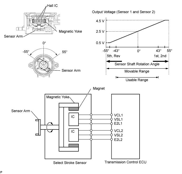
The select stroke sensor is mounted on the shift and select actuator, and detects the select position of the shift and select lever shaft. The sensor consists of a sensor arm, magnetic yoke and 2 Hall ICs. This sensor is a non-contact type, and uses Hall effect elements (Hall ICs: main and sub), in order to yield accurate signals.
When the shift and select actuator is operating in the select direction, the magnetic yoke that is coaxially positioned on the sensor arm is rotated and the magnet position changes. The Hall ICs convert the magnet position change into voltage signals and send them to the transmission control ECU. The transmission control ECU judges the select motor operating condition (which gear shift fork shaft is selected: No. 1, No. 2, No. 3 or Reverse) based on the signal from the select stroke sensor.
The main and sub circuits in the select stroke sensor have the same output characteristics. The sensor construction and operation of the select stroke sensor are basically the same as those of the clutch stroke sensor.
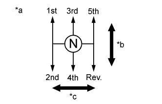
| *a | Shift and Select Actuator Operation |
| *b | Shift Direction |
| *c | Select Direction |
| DTC No. | DTC Detection Condition | Trouble Area |
|---|---|---|
| P0905 | Deviation between sensor signal 1 (main) and sensor signal 2 (sub) is 2.0 mm (0.078 in.) or more for 1.0 second or more (1-trip detection logic) |
|
| P0906 | Select stroke sensor (main) signal voltage is 0.2 V or less for 0.5 seconds or more (1-trip detection logic) |
|
| Select stroke sensor (sub) signal voltage is 0.2 V or less for 0.5 seconds or more (1-trip detection logic) |
||
| P0907 | Select stroke sensor (main) signal voltage is 4.8 V or more for 0.5 seconds or more (1-trip detection logic) |
|
| Select stroke sensor (sub) signal voltage is 4.8 V or more for 0.5 seconds or more (1-trip detection logic) |
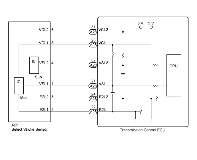
WIRING DIAGRAM
INSPECTION PROCEDURE
Note
In select stroke sensor replacement, perform [Initialization and Learning] Click here and [Synchronization Position Calibration] Click here after installing the sensor.
If the sensor is installed without performing [Initialization and Learning] procedure and [Synchronization Position Calibration] procedure, it may cause driving performance degradation or system component breakage.
PROCEDURE
-
INSPECT TRANSMISSION CONTROL ECU (VCL1 AND VCL2 VOLTAGE)
-
Disconnect the select stroke sensor connector.
-
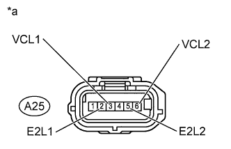
Text in Illustration *a Front view of wire harness connector
(to Select Stroke Sensor)
Turn the ignition switch to ON.
-
Measure the voltage according to the value(s) in the table below.
Standard Voltage Tester Connection Switch Condition Specified Condition A25-5 (E2L2) - A25-6 (VCL2) Ignition Switch ON 4.7 to 5.3 V A25-2 (E2L1) - A25-3 (VCL1) Ignition Switch ON 4.7 to 5.3 V
NG 
CHECK HARNESS AND CONNECTOR (SELECT STROKE SENSOR - TRANSMISSION CONTROL ECU) Click here
OK 
-
-
INSPECT SELECT STROKE SENSOR
-
Remove the select stroke sensor.
-
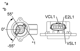
Text in Illustration *1 Sensor Arm *a Component without harness connected
(Select Stroke Sensor)
*b Main Measure the voltage between the terminals of the select stroke sensor connector (main).
-
Prepare 3 dry cell batteries (1.5 V) and 2 leads for connecting the batteries and the sensor.
-
Connect the batteries in series.
-
Connect the positive battery terminal to sensor terminal 3 (VCL1), and the negative battery terminal to sensor terminal 2 (E2L1).
-
Measure the voltage according to the value(s) in the table below.
Standard Voltage (combined dry cell battery voltage of 4.5 V) Tester Connection Condition
(Sensor Angle)
Specified Condition 1 (VSL1) - 2 (E2L1) 55° Approximately 4.05 V 0° Approximately 2.25 V -55° Approximately 0.45 V Reference Voltage (combined dry cell battery voltage of 5.0 +/- 0.3 V) Tester Connection Condition
(Sensor Angle)
Specified Condition 1 (VSL1) - 2 (E2L1) 55° Approximately 4.5 V 0° Approximately 2.5 V -55° Approximately 0.5 V
-
-
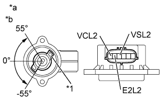
Text in Illustration *1 Sensor Arm *a Component without harness connected
(Select Stroke Sensor)
*b Sub Measure the voltage between the terminals of the select stroke sensor connector (Sub).
-
Connect the positive battery terminal to sensor terminal 6 (VCL2), and the negative battery terminal to sensor terminal 5 (E2L2).
-
Measure the voltage according to the value(s) in the table below.
Standard Voltage (combined dry cell battery voltage of 4.5 V) Tester Connection Condition
(Sensor Angle)
Specified Condition 4 (VSL2) - 5 (E2L2) 55° Approximately 4.05 V 0° Approximately 2.25 V -55° Approximately 0.45 V Reference Voltage (combined dry cell battery voltage of 5.0 +/- 0.3 V) Tester Connection Condition
(Sensor Angle)
Specified Condition 4 (VSL2) - 5 (E2L2) 55° Approximately 4.5 V 0° Approximately 2.5 V -55° Approximately 0.5 V Note
-
Do not apply more than 6 V
-
Do not use a sensor which has been dropped.
-
-
NG
REPLACE SELECT STROKE SENSOR Click here
OK
-
-
CHECK HARNESS AND CONNECTOR (SELECT STROKE SENSOR - TRANSMISSION CONTROL ECU)
-
Disconnect the A28 transmission control ECU connector.
-
Measure the resistance according to the value(s) in the table below.
Standard Resistance Tester Connection Condition Specified Condition A25-4 (VSL2) - A28-32 (VSL2) Always Below 1 Ω A25-1 (VSL1) - A28-21 (VSL1) Always Below 1 Ω A28-21 (VSL1) - Body ground Always 10 kΩ or higher A28-32 (VSL2) - Body ground Always 10 kΩ or higher
NG 
REPAIR OR REPLACE HARNESS OR CONNECTOR
OK
-
-
REPLACE TRANSMISSION CONTROL ECU
-
Replace the transmission control ECU Click here.
NEXT
-
-
PERFORM INITIALIZATION
-
Perform the initialization and learning for multi-mode manual transaxle system Click here.
NEXT 
END
-
-
CHECK HARNESS AND CONNECTOR (SELECT STROKE SENSOR - TRANSMISSION CONTROL ECU)
-
Disconnect the A28 transmission control ECU connector.
-
Measure the resistance according to the value(s) in the table below.
Standard Resistance Tester Connection Condition Specified Condition A25-6 (VCL2) - A28-31 (VCL2) Always Below 1 Ω A25-5 (E2L2) - A28-24 (E2L2) Always Below 1 Ω A25-3 (VCL1) - A28-20 (VCL1) Always Below 1 Ω A25-2 (E2L1) - A28-22 (E2L1) Always Below 1 Ω A28-20 (VCL1) - Body ground Always 10 kΩ or higher A28-22 (E2L1) - Body ground Always 10 kΩ or higher A28-24 (E2L2) - Body ground Always 10 kΩ or higher A28-31 (VCL2) - Body ground Always 10 kΩ or higher
NG
REPAIR OR REPLACE HARNESS OR CONNECTOR
OK
-
-
REPLACE TRANSMISSION CONTROL ECU
-
Replace the transmission control ECU Click here.
NEXT
-
-
PERFORM INITIALIZATION
-
Perform the initialization and learning for multi-mode manual transaxle system Click here.
NEXT
END
-
-
REPLACE SELECT STROKE SENSOR
-
Replace the select stroke sensor Click here.
NEXT
-
-
PERFORM INITIALIZATION
-
Perform the initialization and learning for multi-mode manual transaxle system Click here.
NEXT
END
-