MULTI-MODE MANUAL TRANSAXLE SYSTEM, Diagnostic DTC:P0885, P0887

| DTC Code | DTC Name |
|---|---|
| P0885 | TCM Power Relay Control Circuit / Open |
| P0887 | TCM Power Relay Control Circuit (Short) |
DESCRIPTION
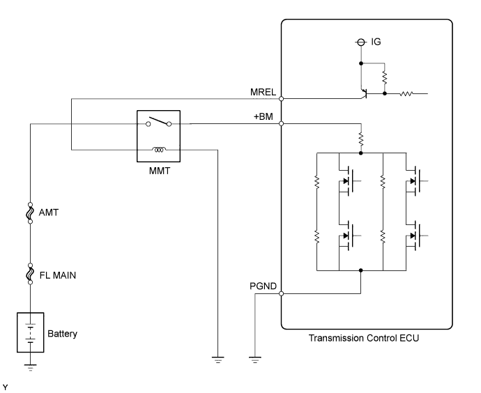
The multi-mode manual transmission system has a dedicated power supply circuit. While the ignition switch is turned to ON, the transmission control ECU outputs the power from the MREL terminal to operate the MMT relay. Then, the power is supplied to the +BM terminal of the transmission control ECU through the MMT relay. The voltage (+BM) is monitored and when it is low (6.29 V or less) despite the voltage is supplied to MREL circuit, the transmission control ECU determines that there is a malfunction in the multi-mode manual transmission system and sets a DTC. When the voltage (+BM) is high (6.29 V or more) although the voltage is not supplied to the MREL circuit, the transmission control ECU sets a DTC.
| DTC No. | DTC Detecting Conditions | Trouble Areas |
|---|---|---|
| P0885 | The transmission control ECU detects the following conditions simultaneously: (1 trip detection logic)
|
|
| P0887 | The transmission control ECU detects the following conditions simultaneously: (1 trip detection logic)
|
|
WIRING DIAGRAM
INSPECTION PROCEDURE
PROCEDURE
-
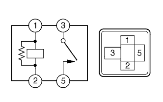
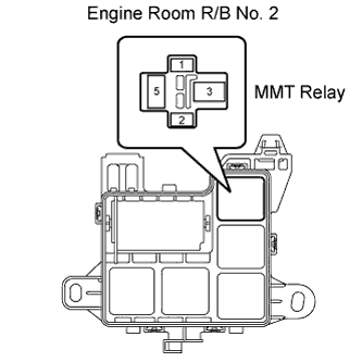
INSPECT RELAY
-
Remove the MMT relay from the engine room R/B No. 2.
-
Check the resistance.
Standard Resistance Tester Connections Specified Conditions 3 - 5 10 kΩ or higher 3 - 5 Below 1 Ω
When battery voltage applied to terminal 1 and 2
-
Reinstall the MMT relay.
NG 
REPLACE RELAY
OK 
-
-
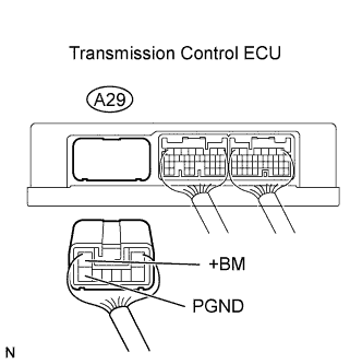
INSPECT TRANSMISSION CONTROL ECU ASSEMBLY (+BM TERMINAL INPUT VOLTAGE)
-
Disconnect the transmission control ECU connector.
-
Turn the ignition switch to ON.
-
Measure the voltage between the terminals of the transmission control ECU connector.
Standard Voltage Tester Connections Specified Conditions +BM (A29-2) - PGND (A29-8) 10 to 14 V -
Turn the ignition switch to OFF.
-
Measure the voltage between the terminals of the transmission control ECU connector.
Standard Voltage Tester Connections Specified Conditions +BM (A29-2) - PGND (A29-8) Below 1 V -
Reconnect the transmission control ECU connector.
OK
REPLACE TRANSMISSION CONTROL ECU ASSEMBLY
NG
-
-
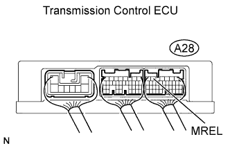
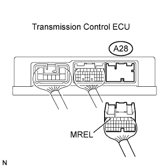
INSPECT TRANSMISSION CONTROL ECU ASSEMBLY (MREL TERMINAL OUTPUT VOLTAGE)
-
Measure the voltage between the terminal of the transmission control ECU and the body ground when the ignition switch is turned to ON and OFF.
Standard Voltage Tester Connections Ignition Switch Specified Conditions MREL (A28-5) - Body
ground
OFF Below 1 V MREL (A28-5) - Body
ground
ON 10 to 14 V
NG 
CHECK HARNESS AND CONNECTOR (CHECK FOR SHORT BETWEEN MREL AND GND) Click here
OK 
REPAIR OR REPLACE HARNESS AND CONNECTOR (MREL - MMT RELAY - GND, +BM - MMT RELAY - BATTERY)
-
-
CHECK HARNESS AND CONNECTOR (CHECK FOR SHORT BETWEEN MREL AND GND)
-
Disconnect the transmission control ECU connectors.
-
Remove the MMT relay from the engine room R/B No. 2.
-
Check the resistance.
Standard Resistance (Check for Short) Tester Connections Specified Conditions MREL (A28-5) - Body ground 10 kΩ or higher -
Reconnect the transmission control ECU connectors.
-
Reinstall the relay.
NG
REPAIR OR REPLACE HARNESS OR CONNECTOR
OK
REPLACE TRANSMISSION CONTROL ECU ASSEMBLY
-