MULTI-MODE MANUAL TRANSAXLE SYSTEM, Diagnostic DTC:P0821

| DTC Code | DTC Name |
|---|---|
| P0821 | Gear Lever "X" Position Circuit |
DESCRIPTION
Based on the signal from the transmission shift main switch, the transmission control ECU detects whether the shift lever position is in the E or M position. If the shift lever position switch is ON despite the shift lever position being N or R, the transmission control ECU sets the DTC.
For more details of the transmission shift main switch, refer to DTC P0820 Click here.
| DTC No. | DTC Detection Condition | Trouble Area |
|---|---|---|
| P0821 | The transmission control ECU detects the following conditions simultaneously for 1.0 second: (1-trip detection logic)
|
|
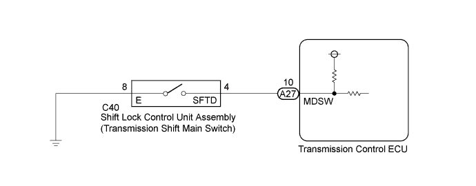
WIRING DIAGRAM
INSPECTION PROCEDURE
PROCEDURE
-
INSPECT SHIFT LOCK CONTROL UNIT ASSEMBLY (TRANSMISSION SHIFT MAIN SWITCH)
-
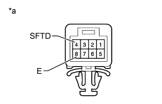
Text In Illustration *a Component without harness connected
Shift Lock Control Unit Assembly (Transmission Shift Main Switch)
Disconnect the C40 shift lock control unit connector.
-
Measure the resistance according to the value(s) in the table below.
Standard Resistance Tester Connection Switch Condition Specified Condition 4 (SFTD) - 8 (E) Shift lever in
R, N or E
10 kΩ or higher Shift lever in
M, + or -
Below 1 Ω
NG 
REPLACE SHIFT LOCK CONTROL UNIT ASSEMBLY Click here
OK 
-
-
CHECK HARNESS AND CONNECTOR (SHIFT LOCK CONTROL UNIT ASSEMBLY - TRANSMISSION CONTROL ECU)
-
Disconnect the A27 transmission control ECU connector.
-
Measure the resistance according to the value(s) in the table below.
Standard Resistance Tester Connection Condition Specified Condition A27-10 (MDSW) - C40-4 (SFTD) Always Below 1 Ω A27-10 (MDSW) - Body ground Always 10 kΩ or higher
NG
REPAIR OR REPLACE HARNESS OR CONNECTOR
OK
-
-
CHECK HARNESS AND CONNECTOR (SHIFT LOCK CONTROL UNIT ASSEMBLY - BODY GROUND)
-
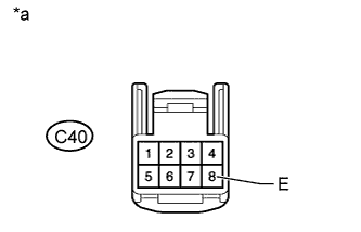
Text in Illustration *a Front view of wire harness connector
(to Shift Lock Control Unit Assembly)
Measure the resistance according to the value(s) in the table below.
Standard Resistance Tester Connection Condition Specified Condition C40-8 (E) - Body ground Always Below 1 Ω
NG
REPAIR OR REPLACE HARNESS OR CONNECTOR
OK
-
-
REPLACE TRANSMISSION CONTROL ECU
-
Replace the transmission control ECU Click here.
NEXT
-
-
PERFORM INITIALIZATION
-
Perform the initialization and learning for multi-mode manual transaxle system Click here.
NEXT 
END
-