MULTI-MODE MANUAL TRANSAXLE UNIT REASSEMBLY

-
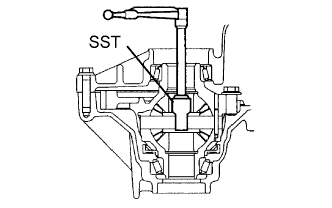
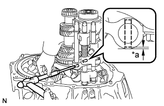
INSTALL TRANSAXLE CASE STRAIGHT PIN
-
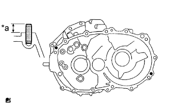
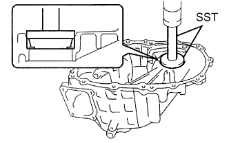
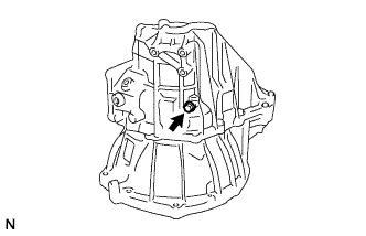
Text in Illustration *a Standard Depth Install the transaxle case straight pin.
Standard depth 10.5 to 11.5 mm (0.4134 to 0.4528 in.)
-
-
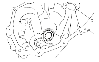
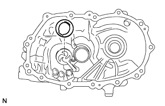
INSTALL OUTPUT SHAFT(MTM) COVER
-
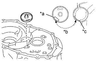
Text in Illustration *a Hole *b Align *c Groove Install the output shaft (MTM) cover as shown in the illustration.
-
-
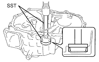
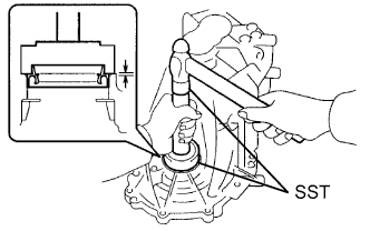
INSTALL OUTPUT SHAFT FRONT BEARING
-
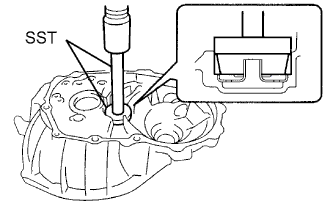
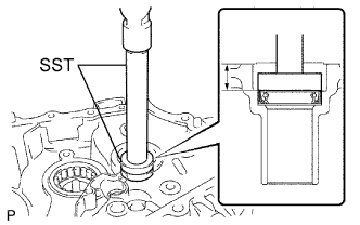
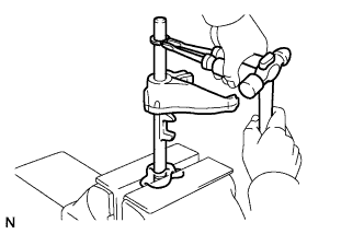
Using SST and a press, press in the output shaft front bearing (outer race).
- SST
- 09950-60010 ( 09951-00510 )
- 09950-70010 ( 09951-07150 )
-
-
INSTALL FR0NT DIFFERENTIAL CASE FRONT TAPERED ROLLER BEARING
-
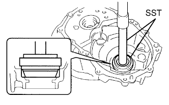
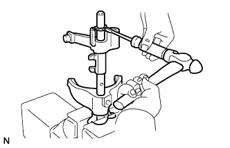
Using SST and a press, press in the front differential case front tapered roller bearing (outer race).
- SST
- 09350-32014 ( 09351-32111, 09351-32130 )
-
-
INSTALL FRONT DIFFERENTIAL CASE REAR TAPERED ROLLER BEARING
-
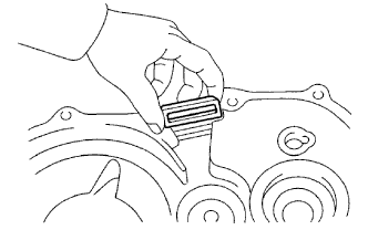
Install the shim onto the manual transmission case.
Tech Tips
When re-using the output shaft rear tapered roller bearing, first install a shim of the same thickness as before. If installing a new output shaft rear tapered roller bearing, first select and install a shim which is thinner than the original.
-
Using SST and a press, press in the FR differential case rear tapered roller bearing (outer race).
- SST
- 09950-60010 ( 09951-00620 )
- 09950-70010 ( 09951-07100 )
-
-
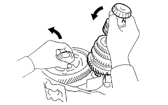
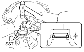
INSPECT DIFFERENTIAL SIDE BEARING PRELOAD
-
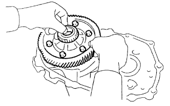
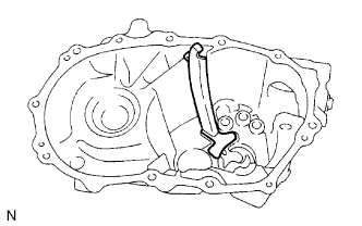
Coat the differential case assembly with gear oil, and install it onto the front transaxle case.
-
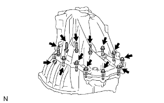
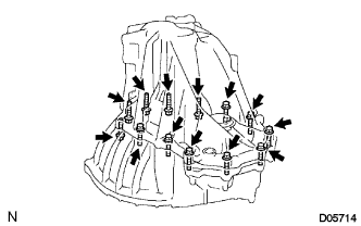
Install the manual transmission case with the 13 bolts.
- Torque:
- 29 N*m { 300 kgf*cm, 22 ft.*lbf }
Tech Tips
Manual transmission case side: 8 bolts
Front transaxle case side: 5 bolts
-
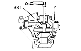
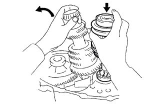
Using SST and a torque wrench, turn the differential case assembly right and left 2 or 3 times to allow the bearings to settle.
- SST
- 09564-32011
-
Using SST and a torque wrench, measure the preload.
- SST
- 09564-32011
Preload (at starting) New bearing 0.78 to 1.57 N*m (7.95 to 16.00 kgf*cm, 6.9 to 13.89 in.*lbf) Used bearing 0.49 to 0.98 N*m (5.00 to 9.99 kgf*cm, 4.3 to 8.67 in.*lbf) -
Select another shim.
Shim Thickness Mark Thickness
mm (in.)
Mark Thickness
mm (in.)
Mark Thickness
mm (in.)
01 1.10 (0.433) 08 1.45 (0.0571) 15 1.80 (0.0709) 02 1.15 (0.0453) 09 1.50 (0.0591) 16 1.85 (0.0728) 03 1.20 (0.0472) 10 1.55 (0.0610) 17 1.90 (0.0748) 04 1.25 (0.04952) 11 1.60 (0.0630) 18 1.95 (0.0768) 05 1.30 (0.0512) 12 1.65 (0.0650) 19 2.00 (0.0787) 06 1.35 (0.0531) 13 1.70 (0.0669) - - 07 1.40 (0.0551) 14 1.75 (0.0689) - - -
Remove the 13 bolts and the manual transmission case from the front transaxle case.
-
Remove the differential case assembly from the front transaxle case.
-
-
INSTALL OUTPUT SHAFT REAR BEARING
-
Install the output shaft rear bearing shim onto the manual transmission case.
Tech Tips
When re-using the output shaft rear tapered roller bearing, first install a shim of the same thickness as before. If installing a new output shaft rear tapered roller bearing, first select and install a shim which is thinner than the original.
-
Using SST and a press, press in the output shaft rear bearing (outer race).
- SST
- 09950-60010 ( 09951-00570 )
- 09950-70010 ( 09951-07200 )
-
-
ADJUST OUTPUT SHAFT BEARING PRELOAD
-
Install the output shaft assembly and the differential case assembly onto the front transaxle case.
-
Install the manual transmission case onto the front transaxle case with the 13 bolts.
- Torque:
- 29 N*m { 300 kgf*cm, 22 ft.*lbf }
-
Using SST and a torque wrench, turn the output shaft assembly and differential case assembly right and left 2 or 3 times to allow the bearings to settle.
- SST
- 09564-32011
-
Using SST and a torque wrench, measure the preload.
- SST
- 09564-32011
Preload (at starting) New bearing 2.79 to 5.56 N*m (28.4 to 56.7 kgf*cm, 24.7 to 49.2 in.*lbf) Used bearing 1.73 to 3.47 N*m (17.6 to 35.4 kgf*cm, 15.3 to 30.7 in.*lbf) -
Select another output shaft rear bearing shim.
Shim Thickness Mark Thickness
mm (in.)
Mark Thickness
mm (in.)
A 1.55 (0.0610) J 1.95 (0.0768) B 1.60 (0.0630) K 2.00 (0.0787) C 1.65 (0.0650) L 2.05 (0.0807) D 1.70 (0.0669) M 2.10 (0.0827) E 1.75 (0.0689) N 2.15 (0.0846) F 1.80 (0.0709) P 2.20 (0.0866) G 1.85 (0.0728) Q 2.25 (0.0886) H 1.90 (0.0748) -
Remove the 13 bolts and the manual transmission case from the front transaxle case.
-
Remove the output shaft assembly from the front transaxle case.
-
Remove the differential case assembly from the front transaxle case.
-
-
INSTALL INPUT SHAFT REAR BEARING SHIM
-
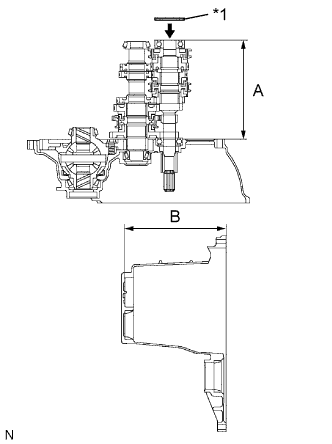
Text in Illustration *1 Input Shaft Rear Bearing Shim Using vernier calipers, accurately measure dimensions A and B.
-
Select an input shaft rear bearing shim that brings the value within the specifications.
Standard Shim thickness (B - A) should be more than 0 mm (0 in.) and less than 0.1 mm (0.0039 in.) Shim Thickness Mark Thickness
mm (in.)
Mark Thickness
mm (in.)
F 1.80 (0.0709) N 2.15 (0.0846) G 1.85 (0.0728) P 2.20 (0.0866) H 1.90 (0.0748) Q 2.25 (0.0886) J 1.95 (0.0768) R 2.30 (0.0906) K 2.00 (0.0787) S 2.35 (0.0925) L 2.05 (0.0807) T 2.40 (0.0945) M 2.10 (0.0827) - - -
Install the input shaft rear bearing shim.
-
-
INSTALL TRANSMISSION CASE OIL SEAL
-
Using SST and a hammer, install a new transmission case oil seal into the manual transmission case.
- SST
- 09950-60010 ( 09951-00370 )
- 09950-70010 ( 09951-07150 )
Drive in depth 2.1 to 3.1 mm (0.083 to 0.122 in.) -
Coat the tip of the transmission oil seal with MP grease.
-
-
INSTALL TRANSAXLE CASE OIL SEAL
-
Using SST and a hammer, install the transaxle case oil seal to the front transaxle case.
- SST
- 09316-60011 ( 09316-00011 )
Drive in depth 1.7 to 2.7 mm (0.067 to 0.106 in.) -
Coat the tip of the transmission case oil seal with MP grease.
-
-
INSTALL FRONT TRANSAXLE CASE OIL SEAL
-
Using SST and a hammer, install the front transaxle case oil seal into the front transaxle case.
- SST
- 09710-20011 ( 09710-06071 )
- 09950-70010 ( 09951-07150 )
Drive in depth 14.4 to 15.4 mm (0.567 to 0.606 in.) -
Coat the tip of the front transaxle case oil seal with MP grease.
-
-
INSTALL TRANSMISSION MAGNET
-
Clean the transmission magnet and then install it onto the front transaxle case.
-
-
INSTALL OIL RECEIVER PIPE NO.2(MTM)
-
Install oil receiver pipe No. 2 onto the manual transmission case.
Note
Do not damage oil receiver pipe No. 2.
-
-
INSTALL FRONT DIFFERENTIAL CASE
-

Coat the differential case tapered roller bearings with gear oil, and install them onto the front transaxle case.
-
-
INSTALL OUTPUT SHAFT
-
Install the output shaft assembly onto the front transaxle case.
-
-
INSTALL INPUT SHAFT
-
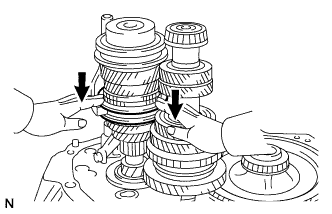
Coat the sliding and rotating surfaces of the input and output shafts assembly with gear oil, and install them onto the front transaxle case.
-
-
INSTALL GEAR SHIFT FORK SHAFT NO.2
-
Install gear shift fork No. 2 onto gear shift fork shaft No. 2.
-
Using a screwdriver and hammer, install a new snap ring onto gear shift fork shaft No. 2.
-
Install the reverse shift fork onto gear shift fork shaft No. 2.
-
Using a screwdriver and hammer, install a new snap ring onto gear shift fork shaft No. 2.
-
Shift hub sleeve No. 2 into the 3rd gear, as shown.
-
Install gear shift fork shaft No. 2 with the 2 snap rings.
-
Install gear shift fork No.2 and reverse shift fork onto the transaxle case.
-
Set gear shift fork No. 2 onto hub sleeve No. 2.
-
Install the set bolt onto gear shift fork No. 2.
- Torque:
- 16 N*m { 160 kgf*cm, 12 ft.*lbf }
-
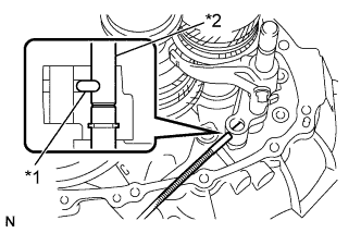
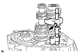
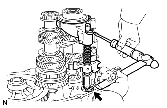
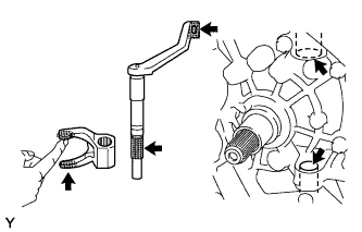
Text in Illustration *1 Straight Pin *2 Gear Shift Fork Shaft No. 2 Using a magnetic finger, install the straight pin into the reverse shift fork.
Note
Insert the straight pin along the groove on gear shift fork shaft No. 2, as shown in the illustration.
-
-
INSTALL REVERSE SHIFT ARM BRACKET ASSEMBLY
-
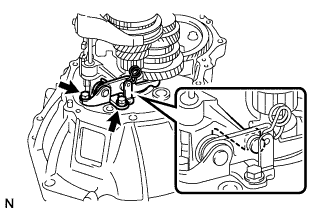
Install the reverse shift arm bracket onto the transaxle case with the 2 bolts.
- Torque:
- 17 N*m { 175 kgf*cm, 13 ft.*lbf }
Note
Fit the edge of the reverse shift fork into the hole in the reverse shift arm bracket.
-
-
INSTALL REVERSE IDLER GEAR SHAFT
-
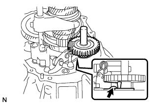
Coat the reverse idler gear shaft with gear oil, and install it onto the transmission case.
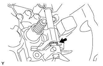
Note
Set the top of the reverse shift arm bracket into the groove on the reverse idler gear, as shown in the illustration.
-
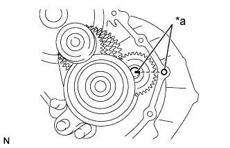
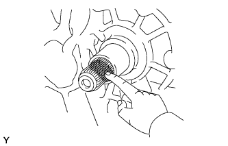
Text in Illustration *a Align Align the mark on the reverse idler gear shaft with the bolt hole, as shown in the illustration.
-
-
INSTALL GEAR SHIFT FORK SHAFT NO.3
-
Install gear shift fork No. 3, the compression spring and gear shift head No. 3 onto gear shift fork shaft No. 3.
-
Install gear shift fork shaft No. 3 onto the transaxle case together with gear shift fork No. 3, the compression spring and shift head No. 3.
-
Set gear shift fork No. 3 onto hub sleeve No. 3.
-
Using a screwdriver and hammer, tap 2 new snap rings onto gear shift fork shaft No. 3.
-
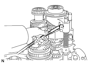
Using a magnetic finger, install the straight pin onto gear shift fork No. 3.
-
-
INSTALL GEAR SHIFT FORK SHAFT NO.1
-
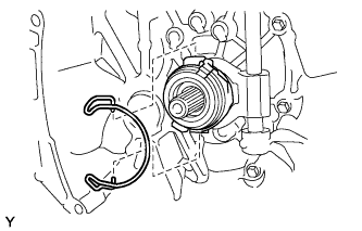
Using a screwdriver and hammer, install a new snap ring onto gear shift fork shaft No. 1.
-
Set gear shift fork No. 1 onto the reverse gear.
-
Set gear shift head No. 1 onto gear shift fork No. 1.
-
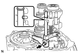
Install gear shift fork shaft No. 1 onto the transaxle case with the snap ring.
Note
Insert the straight pin along the groove on gear shift fork shaft No. 1, as shown in the illustration.
-
Install the set bolt onto gear shift fork No. 1.
- Torque:
- 16 N*m { 160 kgf*cm, 12 ft.*lbf }
-
-
INSTALL SHIFT HEAD SET SLOTTED SPRING PIN
-
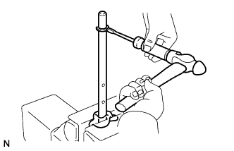
Text in Illustration *a Drive in Depth Using a pin punch and hammer, tap the 2 slotted spring pins into the No. 1 and No. 3 gear shift heads.
Drive in depth -0.5 to 0.5 mm (-0.020 to 0.020 in.)
-
-
INSTALL INPUT SHAFT REAR BEARING SHIM
-
Install the input shaft rear bearing shim onto the transmission case.
Tech Tips
Install the previously selected shim.
-
-
INSTALL MANUAL TRANSMISSION CASE
-
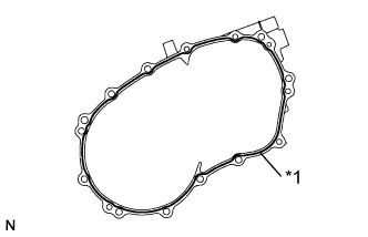
Text in Illustration *1 Seal Packing Apply seal packing to the transmission case, as shown in the illustration.
Seal packing Toyota Genuine Seal Packing 1281, Three Bond 1281 or equivalent Note
Assemble the parts within 10 minutes of application.
-
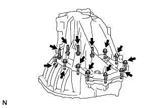
Coat the 13 bolts with adhesive.
Adhesive Toyota Genuine Adhesive 1344, Three Bond 1344 or equivalent -
Install the transmission case onto the transaxle case with the 13 bolts.
- Torque:
- 29 N*m { 300 kgf*cm, 22 ft.*lbf }
-
-
INSTALL REVERSE IDLER GEAR SHAFT BOLT
-
Apply adhesive to the reverse idler gear shaft lock bolt threads.
Adhesive Toyota Genuine Adhesive 1324, Three Bond 1324 or equivalent -
Install the reverse idler gear shaft lock bolt with a new gasket.
- Torque:
- 29 N*m { 300 kgf*cm, 22 ft.*lbf }
-
-
INSTALL TRANSMISSION REVOLUTION SENSOR
-
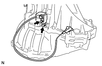
Install a new O-ring onto the transmission revolution sensor.
-
Install the transmission revolution sensor with the bolt.
- Torque:
- 7.8 N*m { 80 kgf*cm, 69 in.*lbf }
-
Install the transmission case protector with the bolt.
- Torque:
- 18 N*m { 185 kgf*cm, 13 ft.*lbf }
-
-
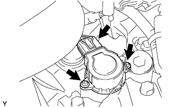
INSTALL SHIFT AND SELECT ACTUATOR ASSEMBLY
-
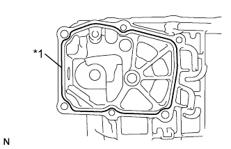
Text in Illustration *1 Seal Packing Apply seal packing to the transmission case as shown.
Seal packing Toyota Genuine Seal Packing 1281, Three Bond 1281 or equivalent -
Apply adhesive to the actuator set bolt threads.
Adhesive Toyota Genuine Adhesive 1344, Three Bond 1344 or equivalent -
Install the shift and select actuator with the 6 bolts and wire harness clamp.
- Torque:
- 18 N*m { 184 kgf*cm, 13 ft.*lbf }
-
-
INSTALL PARK/NEUTRAL POSITION SWITCH ASSEMBLY
-
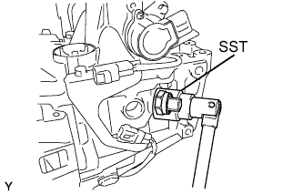
Using SST, install the park/neutral position switch with a new gasket onto the transaxle case.
- Torque:
- 40 N*m { 410 kgf*cm, 30 ft.*lbf }
- SST
- 09817-16011
-
-
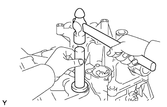
INSTALL LOCK BALL ASSEMBLY NO.1
-
Apply adhesive to the lock ball assembly threads.
Adhesive Toyota Genuine Adhesive 1344, Three Bond 1344 or equivalent -
Using an 18 mm socket wrench, install the lock ball assembly onto the transmission case.
- Torque:
- 37 N*m { 375 kgf*cm, 27 ft.*lbf }
-
-
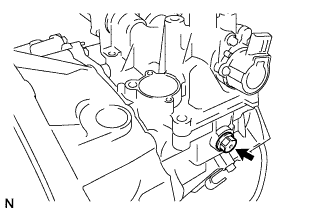
INSTALL BACK-UP LIGHT SWITCH ASSEMBLY
-
Using SST, install the back-up light switch with a new gasket onto the transaxle case.
- SST
- 09817-16011
- Torque:
- 40 N*m { 410 kgf*cm, 30 ft.*lbf }
-
-
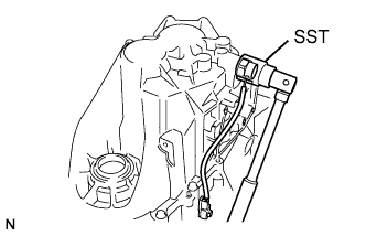
INSTALL CLUTCH RELEASE FORK LEVER SHAFT OIL SEAL
-
Using SST, drive in the oil seal until its surface is flush with the transaxle housing.
- SST
- 09950-60010
- 09950-70010
-
-
INSTALL CLUTCH RELEASE FORK
-
Apply release hub grease to the release fork, fork lever and fork lever bushings.
Grease Toyota Genuine Release Hub Grease or equivalent -
Apply clutch spline grease to the input shaft spline.
Grease Toyota Genuine Clutch Spline Grease or equivalent -
Install the fork lever and fork onto the transaxle housing.
-
Install a new E-ring onto the fork lever.
-
Install the release bearing with the clip.
-
-
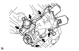
INSTALL SHIFT STROKE SENSOR

-
Apply MP grease to a new O-ring.
-
Install the new O-ring onto the stroke sensor.
-
Set the stroke senor so that the sensor side and the actuator side sensor arms are in the positions shown in the illustration.
-
Turn the stroke sensor clockwise and fix it with the 2 screws.
- Torque:
- 2.0 N*m { 20 kgf*cm, 18 in.*lbf }
-
Connect the shift stroke sensor connector.
-