MULTI-MODE MANUAL TRANSAXLE ASSEMBLY REMOVAL

-
PRECAUTION
Note
After turning the ignition switch off, waiting time may be required before disconnecting the cable from the battery terminal. Therefore, make sure to read the disconnecting the cable from the battery terminal notice before proceeding with work Click here.
-
CLUTCH POSITION ADJUSTMENT
Tech Tips
-
The multi-mode manual transmission system has a load controlled clutch cover (adjustment system). The pressure plate moves depending on the wear quantity of the clutch disc lining.
-
When removing or installing any parts related to the multi-mode manual transmission system, move the clutch actuator to the clutch clamp position. This is for normal operation of the load controlled clutch cover (adjustment system).
-
If the clutch position adjustment operation input fails, perform the operation again from step (a) more than 15 seconds after turning the ignition switch to OFF.
Note
Do not depress the brake pedal while performing the clamp position adjustment using an intelligent tester.
-
Prepare the vehicle:
-
Stop the vehicle.
-
Shift the lever into the N position.
-
Turn the ignition switch to OFF.
-
Apply the parking brake.
-
-
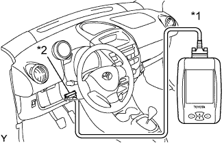
Text in Illustration *1 Intelligent Tester *2 DLC3 Connect the intelligent tester to the DLC3.
-
Turn the ignition switch to ON.
-
Turn the intelligent tester ON.
-
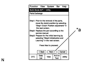
Select the following menu items: Powertrain / Multi-Mode M/T / Utility / Parts Exchange.
-
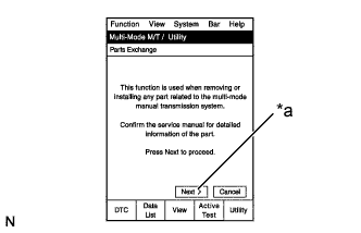
Text in Illustration *a Next Read the information.
-
Press the Next key.
-
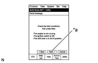
Text in Illustration *a Next Read the information.
-
After checking the vehicle condition, press the Next key.
-
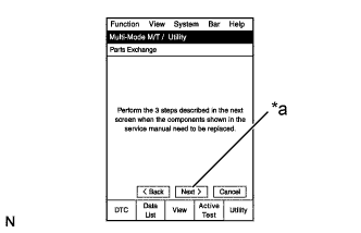
Text in Illustration *a Next Read the information.
-
Press the Next key.
-
Text in Illustration *a Next Read the information.
-
Press the Next key.
-
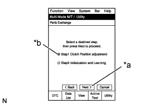
Text in Illustration *a Next *b Step 1 Clutch Position Adjustment On the Multi-Mode M/T / Utility screen, select Step 1 Clutch Position Adjustment (Clamp Position Adjustment).
-
Press the Next key.
-
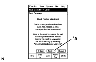
Text in Illustration *a Next Read the information.
-
Press the Next key.
-
Complete Clutch Position Adjustment.
-
Turn the intelligent tester OFF.
-
Turn the ignition switch to OFF.
-
Replace the malfunctioning parts.
Tech Tips
Perform [Initialization and Learning] after repairing the multi-mode manual transmission control system Click here.
-
-
DISCONNECT CABLE FROM NEGATIVE BATTERY TERMINAL
-
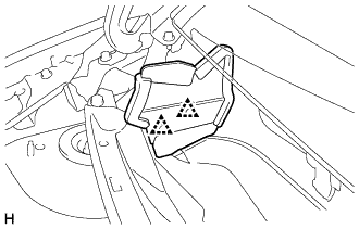
REMOVE STEERING COLUMN HOLE COVER PLATE
-
Turn back the floor carpet and disengage the 2 claws from the steering column hole cover plate.
-
-
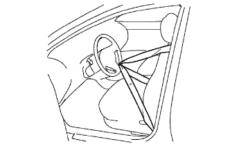
SEPARATE NO. 2 STEERING INTERMEDIATE SHAFT ASSEMBLY
-
Hold the steering wheel assembly with the seat belt in order to prevent rotation and damage to the spiral cable.
-
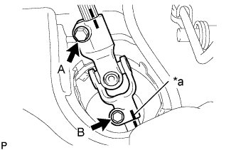
Text in Illustration *a Matchmark Place matchmarks on the No. 2 steering intermediate shaft assembly and the steering gear assembly.
-
Loosen bolt A and remove bolt B to separate the No. 2 steering intermediate shaft assembly.
-
-
SEPARATE NO. 1 STEERING COLUMN HOLE COVER SUB-ASSEMBLY
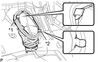
Text in Illustration *1 Clip A *2 Clip B
-
Remove clip A and separate the No. 1 steering column hole cover sub-assembly from the body.
Note
Do not damage clip B.
-
-
REMOVE FRONT WHEELS
-
DRAIN TRANSAXLE OIL
-
Remove the filler plug and gasket.
-
Remove the drain plug and gasket, and drain the oil.
-
Install the drain plug with a new gasket.
- Torque:
- 39 N*m { 400 kgf*cm, 29 ft.*lbf }
-
-
REMOVE FRONT WIPER MOTOR AND LINK ASSEMBLY
-
REMOVE FRONT AIR SHUTTER SEAL RH
-
Remove the 2 clips and front air shutter seal RH.
-
-
REMOVE FRONT NO. 1 VENTILATOR SEAL
-
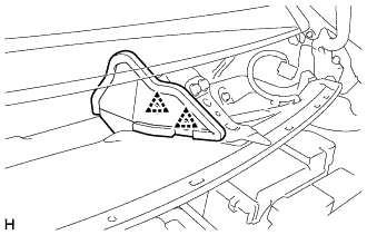
Remove the 2 clips and No. 1 front ventilator seal.
-
-
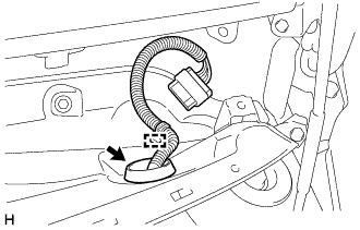
REMOVE COWL TOP PANEL OUTER
-
Disengage the wire harness clamp.
-
Disengage the grommet and separate the wire harness.
-
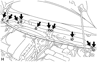
Remove the 10 bolts and the cowl top panel outer.
-
-
REMOVE BATTERY
-
Loosen the nut and disconnect the battery positive (+) terminal.
-
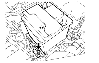
Remove the bolt and the battery clamp.
-
Remove the battery.
-
-
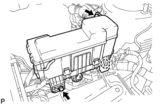
SEPARATE ENGINE ROOM RELAY BLOCK
-
Remove the 2 bolts.
-
Disengage the claw and separate the engine room relay block.
-
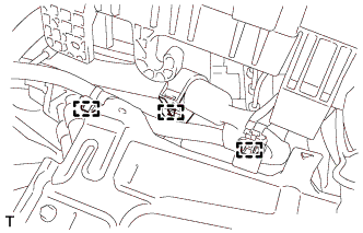
Disengage the 3 wire harness clamps.
-
Provisionally set the engine room relay block to the hood support rod.
-
-
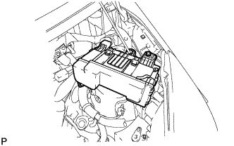
REMOVE BATTERY CLAMP SUB-ASSEMBLY
-
Remove the 3 bolts and the battery clamp sub-assembly.
-
-
REMOVE CLUTCH ACTUATOR ASSEMBLY
-
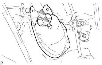
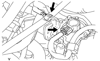
Disconnect the clutch stroke sensor connector and motor connector.
Note
Do not forcibly pull the connector as this may damage the wire harness.
-
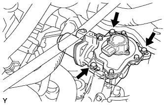
Remove the 3 bolts and clutch actuator assembly.
Note
-
Loosen the bolts slowly, and be careful not to get your fingers caught as the clutch actuator assembly moves due to the reaction force from the clutch cover.
-
Do not drop the removed clutch actuator assembly or subject it to any impacts.
-
-
-
SEPARATE NO. 3 ENGINE WIRE
-
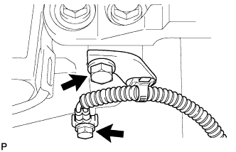
Remove the 2 bolts and separate the No. 3 engine wire (ground cable).
-
-
DISCONNECT CONNECTOR
-
Disconnect the shift stroke sensor connector.
-
Disconnect the select stroke sensor connector.
-
Disconnect the transmission revolution sensor connector.
-
Disconnect the back-up light switch connector.
-
Disconnect the neutral start switch connector.
-
Disconnect the shift and select motor connectors.
-
-
REMOVE STARTER ASSEMBLY
-
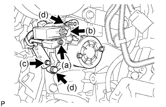
Open the terminal cap, remove the nut and disconnect the wire harness from terminal 50.
-
Open the terminal cap, remove the nut and disconnect the wire harness from terminal 30.
-
Remove the bolt, and wire harness clamp.
-
Remove the 2 bolts, and the starter.
-
-
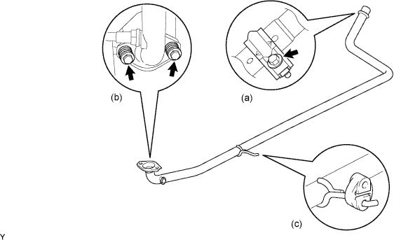
REMOVE EXHAUST FRONT PIPE ASSEMBLY
-
Remove the bolt and clamp.
-
Remove the 2 bolts, 2 compression springs and exhaust pipe gasket.
-
Remove the exhaust pipe No.4 support and exhaust front pipe assembly.
-
-
REMOVE FRONT DRIVE SHAFT ASSEMBLY LH
-
REMOVE FRONT DRIVE SHAFT ASSEMBLY RH
Tech Tips
Use the same procedure for the RH side as for the LH side.
-
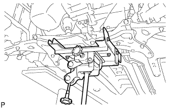
SUSPEND ENGINE ASSEMBLY
-
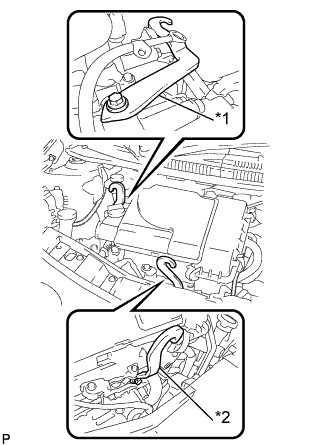
Text in Illustration *1 No. 1 Engine Hanger *2 No. 2 Engine Hanger Install 2 engine hangers with 4 bolts as shown in the illustration.
- Torque:
- 28 N*m { 286 kgf*cm, 21 ft.*lbf }
Tech Tips
No. 1 Engine Hanger 12281 - 40030 No. 2 Engine Hanger 12282 - 40010 Bolt 91671 - 80820 -
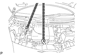
Attach the engine sling device to the engine hangers.
CAUTION:
Do not hang the engine by hooking the chain to any other parts.
-
-
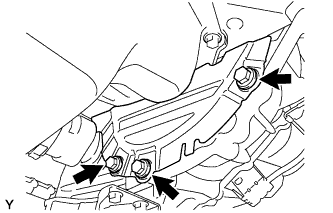
REMOVE FRONT SUSPENSION CROSSMEMBER SUB-ASSEMBLY
-
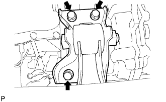
Remove the 3 bolts, then separate the engine mounting control bracket.
-
Using a transmission jack, support the front suspension crossmember sub-assembly.
-
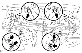
Remove the 6 bolts and the front suspension crossmember sub-assembly.
-
-
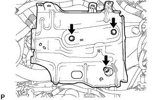
REMOVE FLYWHEEL HOUSING UNDER COVER
-
Remove the 3 bolts and the flywheel housing under cover.
-
-
SUPPORT MULTI-MODE MANUAL TRANSAXLE ASSEMBLY
-
Support the multi-mode manual transaxle assembly with a transmission jack.
-
-
REMOVE TRANSVERSE ENGINE ENGINE MOUNTING INSULATOR
-
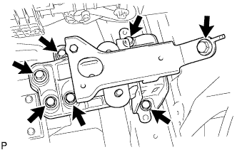
Remove the 7 bolts and the transverse engine engine mounting insulator with the transverse engine engine mounting bracket.
-
-
REMOVE MULTI-MODE MANUAL TRANSAXLE ASSEMBLY
-
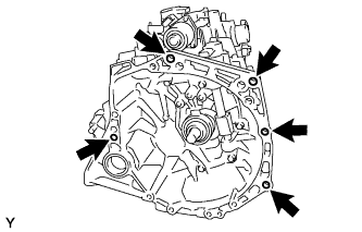
Remove the 5 bolts and the multi-mode manual transaxle assembly from the engine assembly.
-