MULTI-MODE MANUAL TRANSAXLE SYSTEM, Diagnostic DTC:P0725

| DTC Code | DTC Name |
|---|---|
| P0725 | Engine Speed Input Circuit |
DESCRIPTION
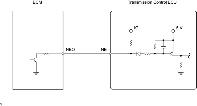
The ECM detects the engine revolution signals (NE) using the crankshaft position (CKP) sensor. The transmission control ECU controls the transmission in accordance with two engine revolution signals. One signal is received directly from the ECM through a serial communication line. The other signal is received from the ECM via the Controller Area Network (CAN) communication. If the transmission control ECU detects no engine revolution signals despite the engine revolution signal via CAN being received while the vehicle is running, the ECU interprets this as a malfunction in the engine revolution signal circuit. The ECU sets the DTC and illuminates the multi-mode manual transmission warning light.
| DTC No. | DTC Detection Conditions | Trouble Areas |
|---|---|---|
| P0725 | The transmission control ECU detects the following conditions simultaneously: (1 trip detection logic)
|
|
WIRING DIAGRAM
INSPECTION PROCEDURE
Note
In ECM replacement, perform the electronic throttle learning after installing the ECM Click here
PROCEDURE
-
CHECK OTHER DTC OUTPUT (IN ADDITION TO DTC P0725)
-
Connect the intelligent tester to the DLC3.
-
Turn the ignition switch to ON and turn the tester ON.
-
Select the following menu items: Powertrain / Multi-Mode M/T / DTC.
-
Read DTCs and write them down.
-
Select the following menu items: Powertrain / Engine and ECT.
-
Read DTCs.
Result Display (DTC Output) Proceed To P0725 A P0725, and P0335 and/or P0336 B Check the DTC output related to the engine revolution signal circuit in the engine control system and the multi-mode manual transmission control system. If DTC P0335 and/or P0336 are set together with DTC P0725, troubleshoot those DTCs first.
B 
GO TO DTC CHART
A 
-
-
READ VALUE USING INTELLIGENT TESTER
-
Connect the intelligent tester to the DLC3.
-
Turn the ignition switch to ON and turn the tester ON.
-
Select the following menu items: Powertrain / Multi-Mode M/T / Data List / Engine Revolution and Backup Engine Speed.
-
Check the engine speed value displayed on the tester.
Items
[Abbreviation]
Measurement Items: Display Normal Conditions Diagnostic Notes Engine Revolution
[Engine Rev]
Engine revolution per minute:
Min.: 0 rpm, Max.: 16,383.75 rpm
790 to 890 rpm: Idling
0 rpm: Engine stopped
If NE signal circuit has a short or open circuit, back-up engine speed data from CAN communication displayed Backup Engine Speed
[Bacup Engin Spd]
Back-up engine speed:
Min.: 0 rpm, Max.: 8,160 rpm
790 to 890 rpm: Idling
0 rpm: Engine stopped
0 rpm displayed when malfunction in CAN communication OK The difference between Engine Revolution value and Backup Engine Speed value is constantly less than 400 rpm.
OK
CHECK FOR INTERMITTENT PROBLEMS
NG
-
-
INSPECT TRANSMISSION CONTROL ECU ASSEMBLY
-
Turn the ignition switch to ON
-
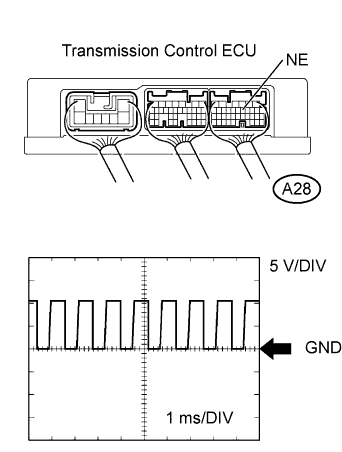
Check the signal waveform between the NE terminal and body ground.
Tester Settings Items Contents Terminals CH1: NE (A28-10) - Body ground Equipment Settings 5 V/DIV, 1 ms/DIV Condition Engine idling OK A waveform similar to that in the illustration is output.
OK
REPLACE TRANSMISSION CONTROL ECU ASSEMBLY
NG
-
-
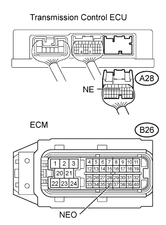
CHECK HARNESS AND CONNECTOR (TRANSMISSION CONTROL ECU - ECM)
-
Disconnect the transmission control ECU connector.
-
Disconnect the ECM connector.
-
Check the resistance.
Standard Resistance Tester connections Specified Conditions NE (A28-10) - NEO (B26-36) Below 1 Ω NE (A28-10) - Body ground 10 kΩ or higher -
Reconnect the transmission control ECU connector.
-
Reconnect the ECM connector.
NG
REPAIR OR REPLACE HARNESS OR CONNECTOR
OK 
REPLACE ECM
-