MULTI-MODE MANUAL TRANSAXLE SYSTEM SYSTEM DESCRIPTION

-
1. MULTI-MODE MANUAL TRANSMISSION SYSTEM OUTLINE
-
The multi-mode manual transmission has been developed from the conventional manual transmission by adding actuators that are directly controlled by electric motors. The transmission control system consists of an electronic throttle control system, clutch actuator, shift and select actuator, sensors, a shift lever, and a transmission control ECU. The system offers automatic clutch operation and two driving modes: automatic shifting E mode and manual shifting M mode.
-
The stroke sensors, which are mounted on each actuator and detect the actuator operating position, are double non-contact type.
-
The multi-mode manual transmission is equipped with a clutch actuator, which has a motor for clutch engagement, and a shift and select actuator, which has two motors for shifting and selecting gear shafts that have been used on the conventional manual transmission. Each actuator operates in accordance with signals from the transmission control ECU. The transmission control ECU receives information from the ECM and sensors, and controls the engine and multi-mode manual transmission.
-
The shift lever features a Shift-by-Wire System that electrically detects the shift lever position chosen by the driver and sends a shift lever position signal to the transmission control ECU to control the transmission.
-
The shift lever has an electrical shift lock mechanism. When the ignition switch is turned to OFF or the shift lever is in the N position with the engine running and the brake pedal released, the shift lever is locked in the current shift position.
-
The multi-mode manual transmission system has fail-safe functions. When the transmission control ECU detects a malfunction in the system, the ECU illuminates the Multi-mode Manual Transmission Warning Light (MMT Warning Light) to inform the driver that a malfunction has occurred. If necessary, the ECU illuminates the Malfunction Indicator Lamp (MIL) and MMT Warning Light simultaneously. Under such conditions, the fail-safe function allows the vehicle to be operated in order to avoid emergency situations.
-
-
FUNCTIONS OF MAIN COMPONENTS
Components Outlines Combination meter (meter ECU) Controls the operation of the indicator lights, and warning light. Multi-mode manual transmission warning light
(built into combination meter)
Illuminates to alert the driver when a malfunction occurs in the multi-mode manual transmission system. Gear position indicator
(built into combination meter)
Indicates the present gear position. The indicator flashes if the actual gear position and the shift lever position do not match. Mode indicator
(built into combination meter)
Indicates E-mode or M-mode. Shift lever position sensor
(built into shift lever assembly)
Outputs the shift lever position and shift request (+ or -) through the ON/OFF combination of 8-contact switches. Transmission shift main switch
(built into shift lever assembly)
Outputs the shift mode signal (E-mode or M-mode). Shift lock solenoid
(built into shift lever assembly)
Actuated by the transmission control ECU. Restricts the movement of the shift lever. Shift motor
(built into shift and select actuator)
Actuated by the transmission control ECU. Effects the shift operation of the shift and select lever shaft.*
Shift stroke sensor
(built into shift and select actuator)
Detects the shift and select actuator operation position (shift direction).*
Select motor
(built into shift and select actuator)
Actuated by the transmission control ECU. Effects the select operation of the shift and select lever shaft.*
Select stroke sensor
(built in shift and select actuator)
Detects the shift and select actuator operation position (select direction).*
Clutch motor
(built into clutch actuator)
Actuated by the transmission control ECU. Engages and disengages the clutch. Clutch stroke sensor
(built into clutch actuator)
Detects the push rod position of the clutch actuator from the rotational angle of the worm wheel in the clutch actuator, and sends the signal to the transmission control ECU. LCC (Load Controlled Clutch cover) The diaphragm spring height of the LCC is adjusted to a predetermined position automatically, in order to apply a constant load to the clutch motor. Transmission revolution sensor Detects the input shaft speed of the transaxle and transmits it to the transmission control ECU. Neutral position switch
(built into transmission assembly)
Detects whether the transmission gear is in neutral. Back-up light switch
(built into transmission assembly)
Detects whether the transmission gear is in reverse, and illuminates the back-up lights. Stop light switch Detects whether the brake pedal is depressed or released. Parking brake switch Detects whether the parking brake lever is applied. Transmission control ECU Controls the multi-mode manual transmission system and signals the ECM to effect engine control during up-shifting or downshifting via CAN (Controller Area Network) communication.
When the multi-mode manual transmission system malfunctions, the transmission control ECU diagnoses and stores the malfunctioning areas. Furthermore, the multi-mode manual transmission warning light and malfunction indicator lamp are illuminated to inform the driver of malfunctions in the system.
Buzzer
(built into transmission control ECU)
Sounds during system warning.
Under performing the initialization and learning or the clamp position adjustment without using intelligent tester, the buzzer sounds to inform the ECU mode change.
ECM Outputs sensor information via CAN communication to the transmission control ECU.
Affects engine control in accordance with signals from the transmission control ECU.
Accelerator pedal position sensor Detects the accelerator pedal position and transmits signals to the ECM. Crankshaft position sensor Detects the engine speed and transmits signals to the transmission control ECU via the ECM. Starter relay The transmission control ECU restricts operation of the starter relay in accordance with the gear position and the braking condition, in order to control the operation of the starter. Tech Tips
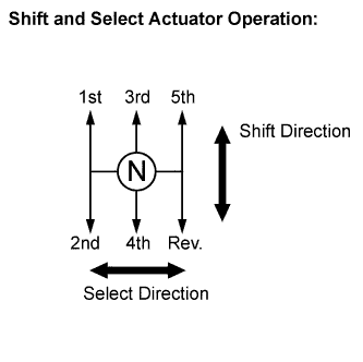
*: Shift and select directions are as shown in the illustration.
-
MULTI-MODE MANUAL TRANSMISSION SYSTEM CONTROL
-
System start:
The multi-mode manual transmission system starts when the ignition switch is turned to ON. The shift lever can be operated when the ignition switch is on and the brake pedal is depressed. The engine starts when the ignition switch is turned to the ST position with the brake pedal depressed and the gear in neutral.
-
Take off/reverse assist control:
When the brake pedal is not depressed with the gear in 1st, 2nd or reverse, the clutch is half-engaged, even if the accelerator pedal is not depressed. As a result, the vehicle can creep slowly like an automatic transmission vehicle. This will assist the vehicle in preparing to move. The take off assist control is cancelled while the parking brake switch is ON.
Tech Tips
When shifting to reverse at a vehicle speed of 6 km/h (3.7 mph) or more, the reverse warning buzzer sounds, and the gear does not shift to reverse.
-
Shift control:
When up-shifting with the accelerator pedal depressed, the ECM restrains engine rev up in accordance with the request signal from the transmission control ECU.
[Automatic shift control (E mode)]
When the shift lever is in the E position, the most appropriate gear is automatically selected in accordance with the accelerator pedal opening angle and vehicle speed. In addition to this automatic shift control, LHD (Left Hand Drive) vehicles have kick down control. When the accelerator pedal is fully depressed until it is felt to click, the ECM for LHD vehicles interprets this as the kick down signal being received. Kick down signals affects the transmission shift control.
[Sequential shift control (M-mode)]
Moving the shift lever to the M position enables the gear selection. The driver can select gears optionally by shifting the lever to the [+] or [-] position.
-
Ascent/descent shift control:
While driving in E-mode, the system operates to prevent excess shifting and obtain the proper driving force and engine brake power by estimating the road inclination based on the vehicle conditions.
[Ascent shift control]
On an ascent, up-shifting to the 3rd, 4th or 5th gear is prohibited, depending on the degree of road inclination.
[Descent shift control]
On a descent, the current gear position is maintained, depending on the degree of road inclination, to obtain engine brake power. When the brake pedal is depressed, the transmission control ECU automatically down shifts to improve the vehicle (driving force) control performance.
-
AI (Artificial Intelligence) shift control:
The AI shift control enables the transmission control ECU to estimate the road conditions and the driver's intention in order to automatically select the optimal shift pattern. This improves ride comfort.
[Accelerator pedal rapid open control]
When the accelerator pedal is rapidly depressed, the system interprets it as an acceleration demand and advances the down-shift timing.
[Accelerator pedal sudden close control]
When the accelerator pedal is suddenly released, the system interprets it as a deceleration demand and ensures the engine brake power without changing gear. This also ensures there is sufficient driving force for the next acceleration stage.
-
Control when the vehicle stops (stopping control):
The transmission control ECU automatically disengages the clutch when the input speed of the transmission revolution sensor falls below a specified speed. This enables the vehicle to stop without stalling. If the shift lever is in the E or M positions, the transmission control ECU shifts the gear to the most appropriate position when the vehicle speed decreases to less than a specified speed.
Tech Tips
If the shift lever is kept in the N position for 2 seconds with the brake pedal released at a specified vehicle speed or less, the transmission control ECU locks the shift lever to prevent improper shift lever operation. When depressing the brake pedal, the shift lever is unlocked.
-
Control when the vehicle is parked (parking control):
When the ignition switch is turned to OFF, the transmission control ECU locks the shift lever in the current position, and 1 second later engages the clutch to park the vehicle with the gear engaged.
Tech Tips
The multi-mode manual transmission system does not have a park position. The vehicle can be parked with the shift lever in any position (N, E, M or R). When the vehicle is parked with the shift lever in a position other than N, the vehicle is parked with the gear engaged. The vehicle may not be parked with the gear engaged if the ignition switch is turned to OFF before the gearshift is complete.
-
-
MULTI-MODE MANUAL TRANSMISSION SYSTEM REMOVAL AND INSTALLATION PROCEDURES
The multi-mode manual transmission differs from the conventional manual transmission. The following operations are necessary when removing and installing the component parts.
-
CLAMP POSITION ADJUSTMENT
-
Preload is applied to the clutch actuator push rod installed on the vehicle.
-
Clamp position adjustment is necessary to position the push rod when the clutch actuator is reinstalled.
-
The push rod position of a new clutch actuator is not suitable for clutch actuator installation. When installing a new clutch actuator, Clamp Position Adjustment must be performed before the installation.
-
The push rod position of a clutch actuator that has been installed on the vehicle is not suitable for clutch actuator reinstallation. Clamp Position Adjustment must be performed when removing the clutch actuator.
-
For details of replacement, refer to CLAMP POSITION ADJUSTMENT Click here.
-
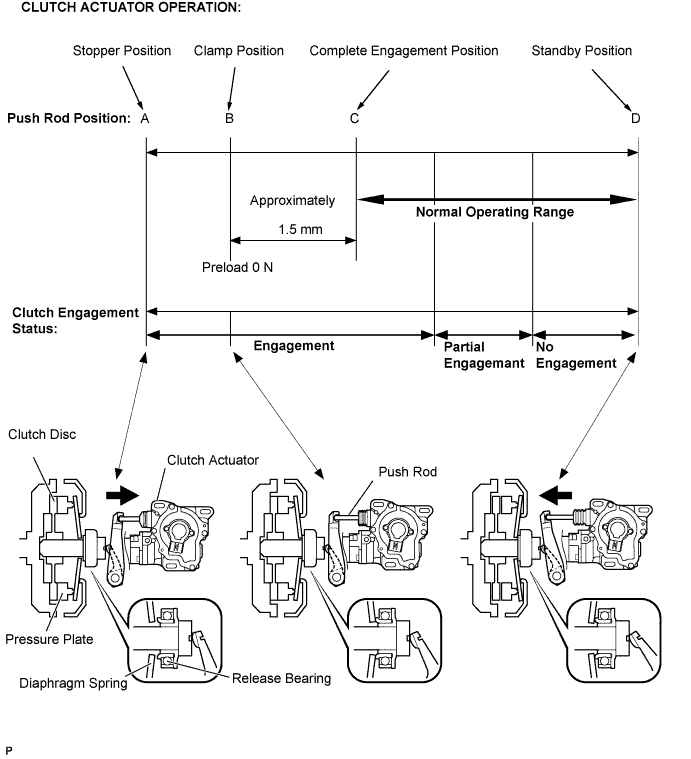
Push rod position A (Stopper position):
The stopper position is where the clutch actuator push rod is fully retracted. Clearance exists between the release bearing and diaphragm spring.
-
Push rod position B (Clutch clamp position):
The clutch clamp position is where 0 N of preload is applied to the diaphragm spring. Removal or installation of the clutch actuator is possible at this point. No clearance exists between the release bearing and diaphragm spring.
-
Push rod position C (Complete engagement position):
During normal clutch operation, the push rod alternates between this position and the standby position (between C and D). When the system is stopped (while the ignition switch is OFF), the push rod maintains this position.
-
Push rod position D (Standby position):
The standby position is where the clutch actuator push rod is protruded and the clutch is not engaged.
-
-
REPLACEMENT OR REMOVAL/INSTALLATION OF MULTI-MODE MANUAL TRANSMISSION SYSTEM PARTS
Refer to the respective pages for each part.
-
INITIALIZATION AND LEARNING
-
INITIALIZATION OF TRANSMISSION SYSTEM:
-
The transmission control ECU stores information from each component, such as sensors and motors, to control the system.
-
Sensors and motors that comprise the multi-mode manual transmission system have individual specification values. The transmission control ECU learns and stores these values, and controls the multi-mode manual transmission system. Therefore, the values stored in the transmission control ECU must be cleared when the sensor or actuator is replaced.
-
Learning of the multi-mode manual transmission system can be performed when there is no learning value in the ECU. It is therefore necessary to perform initialization of the transmission control ECU before performing learning of the multi-mode manual transmission system.
-
For details of replacement, refer to INITIALIZATION AND LEARNING Click here.
-
-
LEARNING OF MULTI-MODE MANUAL TRANSMISSION SYSTEM:
-
This operation is performed to store the individual specification values of components, such as sensors and actuators, in the transmission control ECU.
-
For details of replacement, refer to INITIALIZATION AND LEARNING Click here.
Note
Perform this operation after initialization of the multi-mode manual transmission system.
-
-
-
SYNCHRONIZATION POSITION CALIBRATION
-
The transmission components have individual specification values. The transmission control ECU learns and stores those values, and controls the gearshift accurately. Synchronization position calibration corrects and adjusts the shift points appropriately in accordance with the individual specification values of the components.
-
For details of replacement, Click here.
-
-