MULTI-MODE MANUAL TRANSAXLE SYSTEM PRECAUTION

-
PRECAUTION REGARDING ON-VEHICLE INSPECTION
-
When revving the engine, make sure that the gear is in neutral.
-
-
PRECAUTION REGARDING PARTS REMOVAL AND INSTALLATION
-
When removing or installing parts related to the multi-mode manual transaxle system, perform [Clamp Position Adjustment], [Initialization and Learning] and/or [Synchronization Position Calibration]. In addition, the required operations differ according to the parts to be removed and installed. Proceed with the operation in the order shown in the table below.
Before Removal Part to be Removed Operation Order See Procedure
-
Clutch actuator
-
Transaxle assembly
-
Transaxle parts (inside gear box)
-
Clutch disc and clutch cover
-
Clutch release bearing
-
Clutch release fork
-
Clutch release lever
-
Flywheel
-
Crankshaft
-
Shift and select actuator (with clutch actuator)
-
Clamp Position Adjustment
Before Installation Part to be Installed Operation Order See Procedure
-
New clutch actuator
-
Clamp Position Adjustment
Note
Push rods of brand new clutch actuators (service supply parts) are not set in the clutch clamp position. Therefore, adjust the clamp positions before installing new clutch actuators.
After Installation Part Installed Operation Order See Procedure
-
Transaxle assembly
-
Transaxle parts (inside gear box)
-
Shift and select actuator (with clutch actuator)
-
Transmission control ECU
1. Initialization of Multi-Mode Transaxle System
[Initialization of ECU]
2. Learning of Multi-Mode Manual Transaxle System 3. Synchronization Position Calibration
-
Shift stroke sensor
-
Select stroke sensor
1. Initialization of Multi-Mode Transaxle System
[Initialization of transmission]
2. Learning of Multi-Mode Manual Transaxle System 3. Synchronization Position Calibration
-
Clutch actuator
-
Clutch stroke sensor
-
Clutch disc and clutch cover
-
Clutch release bearing
-
Clutch release fork
-
Clutch release lever
-
Flywheel
-
Crankshaft
1. Initialization of Multi-Mode Transaxle System
[Initialization of clutch]
2. Learning of Multi-Mode Manual Transaxle System Note
-
Replace the clutch disc and clutch cover together. If only one is replaced, the adjustment system of the clutch cover does not function properly. This may cause clutch drag or clutch slippage, which may result in deterioration of drivability or malfunctions of the system parts.
-
After replacing any system components, perform initialization and learning of related components (refer to the operations listed above). If initialization and learning are not performed, the transaxle system will not function properly.
-
Before proceeding with learning of the multi-mode manual transaxle system, clear (initialize) the previously stored learning values. Since the multi-mode manual transaxle system does not have an overwrite function, clearing (initializing) stored data is necessary before the new data can be stored.
-
-
-
EFFECT OF MULTI-MODE MANUAL TRANSAXLE PART MALFUNCTION ON LEARNING
Tech Tips
Use the table below to help determine the cause of learning failure.
Learning Failure by Part Malfunction Part Clutch Position Learning Failure T/M Gear Position Learning Failure Clutch Standby Point Learning Failure Relevant DTC Vehicle speed sensor - - - P0500*3 Battery *1 *1 *1 - Stop light switch - - - P0703*4 Transmission revolution sensor - - Probable cause of error P0715*3 Crankshaft position sensor - - Probable cause of error P0725*5 Clutch stroke sensor *2 *2 *2 P0808*4 Clutch actuator *2 *2 *2 P0900*4 Clutch actuator preload No preload - Possible cause of error Possible cause of error P0810*5 Clamp position adjustment not performed - Possible cause of error Possible cause of error P0810*5 Clutch disc - Possible cause of error Possible cause of error - Shift stroke sensor *2 *2 *2 P0916*4 Shift motor Connector disconnected *2 *2 *2 P0920*4 Not installed correctly - Possible cause of error - - Select stroke sensor *2 *2 *2 P0906*4 Select motor Connector disconnected *2 *2 *2 P0910*4 Not installed correctly - Possible cause of error - - Shift lever position sensor - - - P0820*6 Pattern select switch - - - P0821*6 AMT fuse *2 *2 *2 P0885*4
-
*1: Initial learning cannot be executed due to voltage decrease.
-
*2: Initial learning cannot be executed due to multi-mode manual transaxle part malfunction.
-
*3: DTC can be detected while vehicle running.
-
*4: DTC can be detected when the ignition switch is ON.
-
*5: DTC can be detected during initialization or standby point learning
-
*6: DTC can be detected when shift lever is in R or N.
-
-
PRECAUTIONS REGARDING USE OF SHIFT LOCK RELEASE BUTTON
-
When the vehicle is parked with the shift lever in any position other than N:
-
The engine cannot be started if the shift lever is moved to any position other than N by operating the shift lock release button.
The shift lever should be moved back to N to start the engine.
-
The engine cannot be started if the shift lever is in the position it was in when the vehicle was parked.
The shift lever should be moved back to N to start the engine.
-
When the shift lever is returned to N by operating the shift lock release button, the gear is shifted to neutral when the ignition switch is turned to ON so that the engine can be started.
-
-
When the vehicle is parked with the shift lever in N:
-
The engine can be started even if the shift lever is moved to any position other than N by operating the shift lock release button. In this case, the gear is shifted to the position in accordance with the shift lever position after the engine starts.
Shift Lever Position when Vehicle Parked Current Shift Lever Position Engine Cranking Operation Note Other than N Other than N* Impossible - Other than N Same position in when vehicle parked Impossible - Other than N N* Possible Gear shifted to neutral when ignition switch is ON with brake pedal depressed N Other than N* Possible Gear shifted to position in accordance with shift lever position after engine start N N
(Same position in when vehicle parked)
Possible - N Other than N* Impossible Gear shifted to position other than neutral when ignition switch is ON with brake pedal depressed *: The shift lever was moved with the shift lock release button operation.
-
-
-
OTHER PRECAUTIONS REGARDING MULTI-MODE MANUAL TRANSAXLE SYSTEM
-
Set the gear in neutral when revving the engine.
-
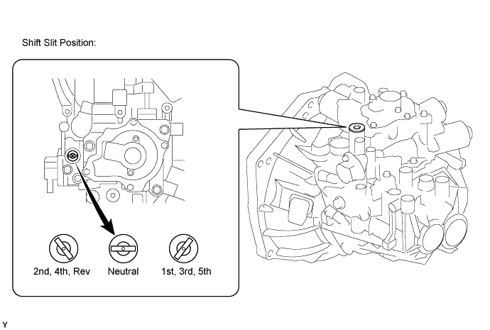
Set the gear to the neutral position before removing the shift and select actuator. If the gear cannot be shifted to the neutral position due to malfunctions of the actuator and/or transaxle gear, remove the plug from the shift and select actuator and observe the position of the shift slit within. If the slit is in any position other than neutral, use a screwdriver to set it to neutral.
-
-
PRECAUTION REGARDING ELECTRONIC THROTTLE CONTROL SYSTEM
-
Perform the electronic throttle learning when the following operations are done Click here.
-
ECM replacement
-
Throttle body assembly replacement
-
-
-
PRECAUTION REGARDING USE OF INTELLIGENT TESTER
Note
-
Read its instruction books before using the tester.
-
Prevent the tester cable from being caught on the pedals, shift lever and steering wheel when driving with the tester connected to the vehicle.
-
When driving the vehicle for testing purposes using the tester, two people are required. One drives the vehicle, and the other operates the tester.
Observe the following items for safety reasons:
-