OUTPUT SHAFT REASSEMBLY

-
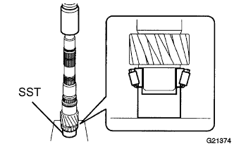
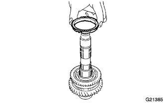
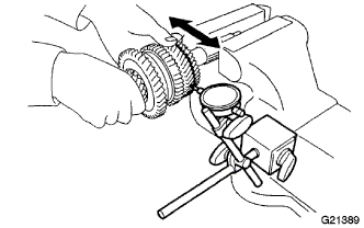
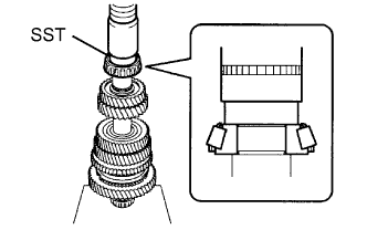
INSTALL OUTPUT SHAFT FRONT BEARING
-
Using SST and a press, install the output shaft front bearing onto the output shaft.
- SST
- 09710-22021 ( 09710-01051 )
-
-
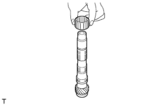
INSTALL 1ST GEAR NEEDLE ROLLER BEARING
-
Coat the 1st gear needle roller bearing with gear oil, and install it onto the output shaft.
-
-
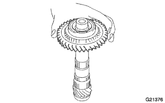
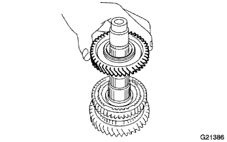
INSTALL 1ST GEAR
-
Coat the 1st gear with gear oil, and install it onto the output shaft.
-
-
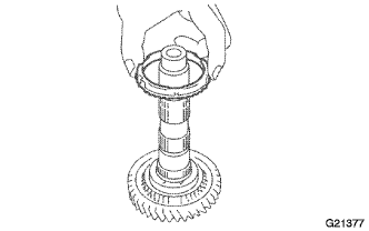
INSTALL 1ST GEAR SYNCHRONIZER RING
-
Coat the 1st gear synchronizer ring with gear oil, and install it onto the 1st gear.
-
-
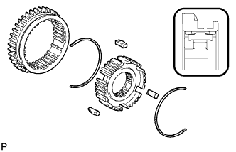
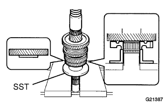
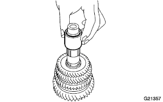
INSTALL NO. 1 TRANSMISSION CLUTCH HUB
-
Install 2 No. 1 shifting key springs, 3 No. 1 shifting keys and the reverse gear onto the No. 1 transmission clutch hub.
-
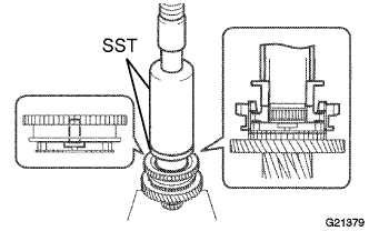
Using SST and a press, install the No. 1 clutch hub onto the output shaft.
- SST
- 09316-60011 ( 09316-00011, 09316-00071 )
Note
Install the reverse gear assembly in the correct orientation, as shown in the illustration.
-
-
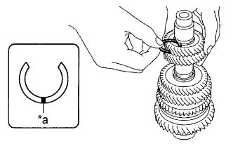
INSTALL NO. 1 CLUTCH HUB SHAFT SNAP RING
-
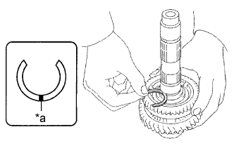
Text in Illustration *a Mark Select a snap ring that allows the minimum axial play.
Standard clearance 0 to 0.1 mm (0 to 0.00393 in.) Snap Ring Thickness Parts No. Mark Thickness
mm (in.)
90520-32014 A 2.28 (0.0898) 90520-32015 B 2.34 (0.0921) 90520-32016 C 2.40 (0.0945) 90520-32017 D 2.46 (0.0969) 90520-32018 E 2.52 (0.0992) 90520-32019 F 2.58 (0.1016) -
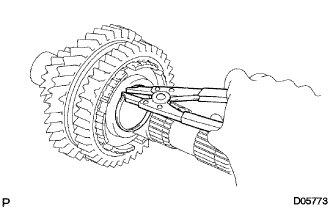
Using a snap ring expander, install the new snap ring onto the output shaft.
-
-
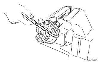
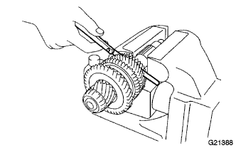
INSPECT 1ST GEAR THRUST CLEARANCE
-
Using a feeler gauge, measure the 1st gear thrust clearance.
Standard clearance 0.10 to 0.35 mm (0.00394 to 0.0137 in.) Maximum clearance 0.35 mm (0.0137 in.)
-
-
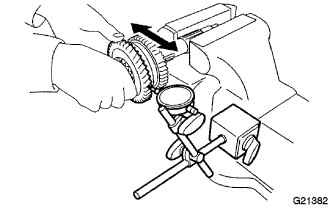
INSPECT 1ST GEAR RADIAL CLEARANCE
-
Using a dial indicator, measure the 1st gear radial clearance.
Standard clearance 0.015 to 0.056 mm (0.000591 to 0.00220 in.) Maximum clearance 0.056 mm (0.00220 in.) If the clearance exceeds the maximum, replace the 1st gear needle roller bearing.
-
-
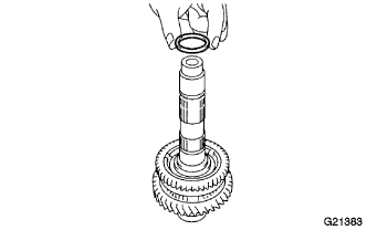
INSTALL 2ND GEAR BEARING SPACER
-
Coat the 2nd gear bearing spacer with gear oil and install it onto the output shaft.
-
-
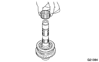
INSTALL 2ND GEAR NEEDLE ROLLER BEARING
-
Coat the 2nd gear needle roller bearing with gear oil, and install it onto the output shaft.
-
-
INSTALL 2ND GEAR SYNCHRONIZER RING
-
Coat the 2nd synchronizer ring with gear oil, and install it onto the reverse gear.
-
-
INSTALL 2ND GEAR
-
Coat the 2nd gear with gear oil, and install it onto the output shaft.
-
-
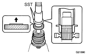
INSTALL 3RD DRIVEN GEAR
-
Using SST and a press, install the 3rd driven gear onto the output shaft.
- SST
- 09316-60011 ( 09316-00041 )
-
-
INSPECT 2ND GEAR THRUST CLEARANCE
-
Using a feeler gauge, measure the 2nd gear thrust clearance.
Standard clearance 0.10 to 0.55 mm (0.00394 to 0.0216 in.) Maximum clearance 0.55 mm (0.0216 in.)
-
-
INSPECT 2ND GEAR RADIAL CLEARANCE
-
Using a dial indicator, measure the 2nd gear radial clearance between the gear and shaft.
Standard clearance 0.015 to 0.056 mm (0.000591 to 0.00220 in.) Maximum clearance 0.056 mm (0.00220 in.) If the clearance exceeds the maximum, replace the 2nd gear needle roller bearing.
-
-
INSTALL OUTPUT SHAFT SPACER
-
Install the output shaft spacer onto the output shaft.
-
-
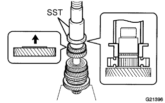
INSTALL 4TH DRIVEN GEAR
-
Using SST and a press, install the 4th driven gear onto the output shaft.
- SST
- 09223-00010
- 09316-60011 ( 09316-00021 )
-
-
INSTALL 5TH DRIVEN GEAR
-
Using SST and a press, install the 5th driven gear onto the output shaft.
- SST
- 09223-00010
- 09316-60011 ( 09316-00021 )
-
-
INSTALL COUNTER 5TH GEAR SHAFT SNAP RING
-
Select a snap ring, using the table below, that makes the thrust clearance of the 5th driven gear less than 0.1 mm (0.00393 in.).
Text in Illustration *a Mark Snap Ring Thickness Parts No. Mark Thickness
mm (in.)
90520-27070 A 2.22 (0.0874) 90520-27071 B 2.28 (0.0898) 90520-27072 C 2.34 (0.0921) 90520-27073 D 2.40 (0.0945) 90520-27074 E 2.46 (0.0969) 90520-27075 F 2.52 (0.0992) 90520-27076 G 2.58 (0.1016) 90520-27077 H 2.64 (0.1039) 90520-27078 J 2.70 (0.1063) -
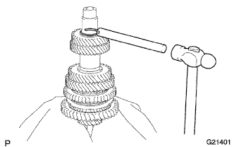
Using a brass bar and hammer, tap the new snap ring onto the output shaft.
-
-
INSTALL OUTPUT SHAFT REAR BEARING
-
Using SST and a press, install the output shaft rear bearing onto the output shaft.
- SST
- 09950-60010 ( 09951-00370 )
-