INPUT SHAFT INSPECTION

-
INSPECT INPUT SHAFT
-
Check the input shaft for wear and damage.
-
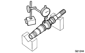
Using a dial indicator, check the input shaft runout.
Maximum runout 0.03 mm (0.00118 in.) If the runout exceeds the maximum, replace the input shaft.
-
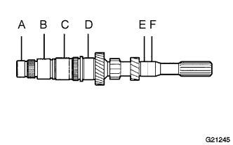
Using a micrometer, measure the outer diameter of the input shaft journal surface.
Standard Measured Part Outer Diameter mm (in.) A 25.502 to 25.515 (1.0041 to 1.0045) B 30.985 to 31.000 (1.2199 to 1.2204) C, D 33.985 to 34.000 (1.3380 to 1.3385) E 23.002 to 23.015 (0.9056 to 0.9061) F 22.967 to 23.000 (0.9043 to 0.9055) If the outer diameter is below the minimum, replace the input shaft.
-
-
INSPECT 3RD GEAR
-
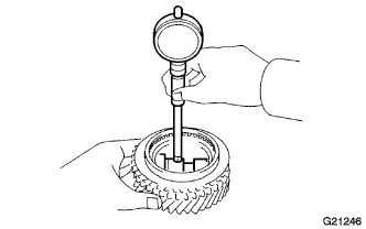
Using a cylinder gauge, measure the inside diameter of the 3rd gear.
Standard inside diameter 39.015 to 39.031 mm (1.5361 to 1.5366 in.) Maximum inside diameter 39.031 mm (1.5366 in.) If the inside diameter exceeds the maximum, replace the 3rd gear.
-
-
INSPECT 4TH GEAR
-
Using a cylinder gauge, measure the inside diameter of the 4th gear.
Standard inside diameter 39.015 to 39.031 mm (1.5361 to 1.5366 in.) Maximum inside diameter 39.031 mm (1.5366 in.) If the inside diameter exceeds the maximum, replace the 4th gear.
-
-
INSPECT 5TH GEAR
-
Using a cylinder gauge, measure the inside diameter of the 5th gear.
Standard inside diameter 36.015 to 36.031 mm (1.4180 to 1.4185 in.) Maximum inside diameter 36.031 mm (1.4185 in.) If the inside diameter exceeds the maximum, replace the 5th gear.
-
-
INSPECT 3RD GEAR SYNCHRONIZER RING
-
Check for wear and damage.
-
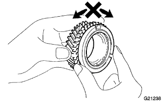
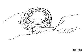
Check the braking effect of the 3rd gear synchronizer ring.
Turn the 3rd gear synchronizer ring in one direction while pushing it against the 3rd gear cone. Check that the ring locks.
-
Using a feeler gauge, measure the clearance between the 3rd gear synchronizer ring back and the 3rd gear spline end.
Standard clearance 0.75 to 1.65 mm (0.0296 to 0.0649 in.) Minimum clearance 0.75 mm (0.0296 in.) If the clearance is below the minimum, replace the 3rd gear synchronizer ring.
-
-
INSPECT 4TH GEAR SYNCHRONIZER RING
-
Check for wear and damage.
-
Check the braking effect of the 4th gear synchronizer ring.
Turn the 4th gear synchronizer ring in one direction while pushing it against the 4th gear cone. Check that the ring locks.
-
Using a feeler gauge, measure the clearance between the 4th synchronizer ring back and the 4th gear spline end.
Standard clearance 0.75 to 1.65 mm (0.0296 to 0.0649 in.) Minimum clearance 0.75 mm (0.0296 in.) If the clearance is below the minimum, replace the 4th gear synchronizer ring.
-
-
INSPECT 5TH GEAR SYNCHRONIZER RING
-
Check for wear and damage.
-
Check the braking effect of the 5th gear synchronizer ring.
Turn the 5th gear synchronizer ring in one direction while pushing it against the 5th gear cone. Check that the ring locks.
-
Using a feeler gauge, measure the clearance between the 5th synchronizer ring back and the 5th gear spline end.
Standard clearance 0.75 to 1.65 mm (0.0296 to 0.0649 in.) Minimum clearance 0.75 mm (0.0296 in.) If the clearance is below the minimum, replace the 5th gear synchronizer ring.
-
-
INSPECT NO. 2 TRANSMISSION HUB SLEEVE
-
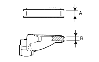
Using a vernier caliper, measure the clearance between the No. 2 transmission hub sleeve and the No. 2 shift fork.
Standard clearance (A-B) 0.15 to 0.35 mm (0.00591 to 0.0137 in.) If the clearance is outside the specifications, replace the No. 2 transmission hub sleeve and No. 2 gear shift fork.
-
-
INSPECT NO. 3 TRANSMISSION HUB SLEEVE
-
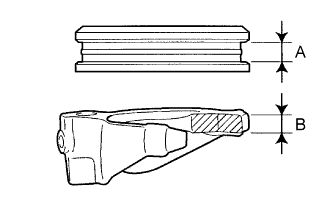
Using a vernier caliper, measure the clearance between the No. 3 transmission hub sleeve and the No. 3 shift fork.
Standard clearance (A-B) 0.15 to 0.35 mm (0.00591 to 0.0137 in.) If the clearance is outside the specifications, replace the No. 3 transmission hub sleeve and No. 3 gear shift fork.
-